
Falkirk Wheel

TheFalkirk Wheel(Scottish Gaelic:Cuibhle na h-Eaglaise Brice) is a rotatingboat liftinTamfourhill,Falkirk,in centralScotland,connecting theForth and Clyde Canalwith theUnion Canal.It opened in 2002 as part of theMillennium Linkproject, reconnecting the two canals for the first time since the 1930s.
The plan to regeneratecentral Scotland's canals and reconnectGlasgowwithEdinburghwas led byBritish Waterwayswith support and funding from seven local authorities, theScottish EnterpriseNetwork, theEuropean Regional Development Fund,and theMillennium Commission.Planners decided early to create a dramatic 21st-century landmark structure to reconnect the canals, instead of simply recreating the historiclock flight.
The wheel raises boats by 24 metres (79 ft), but the Union Canal is still 11 metres (36 ft) higher than the aqueduct which meets the wheel. Boats must also pass through a pair oflocksbetween the top of the wheel and the Union Canal. The Falkirk Wheel is the only rotating boat lift of its kind in the world, and one of two working boat lifts in the United Kingdom, the other being theAnderton Boat Lift.
History
[edit]Pre-1933 link
[edit]
The two canals served by the wheel were previously connected by a series of 11locks.[1][2]With a 35-metre (115 ft) difference in height, it required 3,500 tonnes (3,400 long tons; 3,900 short tons) of water per run and took most of a day to pass through the flight.[3]
By the 1930s these[clarification needed]had fallen into disuse, and the locks were dismantled in 1933.[1][2]The Forth and Clyde Canal closed at the end of 1962,[4]and by the mid-1970s the Union Canal was filled in at both ends, rendered impassable byculvertsin two places and run in pipes under a housing estate.[5]TheBritish Waterways Board(BWB) came into existence on 1 January 1963, the day the Forth and Clyde Canal was closed, with the objective of finding a broad strategy for the future of canals in the United Kingdom.[4][5]
In 1976, the BWB decided after a meeting with local councils that the Forth and Clyde Canal, fragmented by various developments, was to have its remaining navigability preserved by building new bridges with sufficient headroom for boats and continuing to maintain the existing locks.[6]Restoration of sea-to-sea navigation was deemed too expensive at the time, but there were to be no further restrictions on its use.[6]A 1979 survey report documented 69 obstructions to navigation, and sought the opinions of twenty interested parties to present the Forth and Clyde Local (Subject) Plan in 1980.[6]
Proposal
[edit]TheLotteries Act 1993resulted in the creation of theMillennium Commissionto disseminate funds raised by the sale of lottery tickets for selected "good causes".[7]In 1996, when sufficient funds had been accumulated, the Commission invited applications to "do anything they thought desirable... to support worthwhile causes which would mark the year 2000 and the start of the new millennium."[7]The conditions were that the Commission would fund no more than half of the project, with the remaining balance being covered by project backers.[7]
The BWB had made an earlier plan for the reopening of the canal link, which comprehensively covered the necessary work.[7]In 1994, the BWB announced its plan to bid for funding, which was submitted in 1995 on behalf of the Millennium Link Partnership.[8]The plans called for the canals to be opened to their original operating dimensions, with 3 metres (9.8 ft) of headroom above the water. The whole project had a budget of £78 million.[9]
On 14 February 1997, the Commission announced it would support the Link with £32 million of funding, 42% of the project cost.[10]The Wheel and its associated basin was priced at £17 million, more than a fifth of the total budget.[11]Another £46 million had to be raised in the next two years before construction could commence, with contributions from BWB, seven local councils,Scottish Enterprise,and private donations being augmented by £8.6 million from theEuropean Regional Development Fund.[12]
Design
[edit]The Morrison–Bachy Soletanche Joint Venture Team submitted their original design, which resembled aFerris wheelwith four gondolas, in 1999. It was agreed by all parties that the design was functional, but not the showpiece the BWB were looking for.[13][14]After being asked to reconsider, a 20-strong team of architects and engineers was assembled by British Waterways. Under the leadership ofTony Kettlefrom architectsRMJM,the initial concepts and images were created with the mechanical concepts proposed by the design team from Butterley and M G Bennetts. This was an intense period of work, with the final design concept completed in a three-week period during the summer of 1999.[15][13][16]The final design was a co-operative effort between the British Waterways Board, engineering consultantsArup,Butterley Engineeringand RMJM.[12]
Diagrams of gear systems that had been proposed in the very first concepts were modelled by Kettle using his 8-year-old daughter'sLego.Drawings and artist impressions were shown to clients and funders.[15][17]The visitor centre was designed by another RMJM architect,Paul Stallan.[18][19]
Inspirations for the design include a double-headedCeltic axe(abearded axe), the propeller of a ship and the ribcage of a whale.[20]Kettle described the Wheel as "a beautiful, organic flowing thing, like the spine of a fish,"[17]and theRoyal Fine Art Commission for Scotlanddescribed it as "a form of contemporary sculpture."[12]
Models and renderings of the Falkirk Wheel were displayed in a 2012 exhibition at theVictoria and Albert Museumin London.[21]Since 2007, the Falkirk Wheel has been featured on the obverse of the new series of£50 notesissued by theBank of Scotland.The series of notes commemorates Scottish engineering achievements with illustrations of bridges in Scotland such as theGlenfinnan Viaductand theForth Bridge.[22]
Construction
[edit]
In March 1999Donald Dewar,theSecretary of State for Scotland,cut the firstsodof turf to begin work at lock 31 on the Forth and Clyde Canal.[12]Over 1000 people were employed in the construction of the wheel,[23]which was designed to last for at least 120 years.[20][24]
The wheel was fully constructed and assembled at theButterley Engineeringplant inRipley,Derbyshire.The structure was then dismantled in the summer of 2001, and transported on 35 lorry loads to Falkirk, before being reassembled into five sections on the ground and lifted into place.[25]Construction of the canal required 250,000 m3(8,800,000 cu ft) of excavation, a 160 m (520 ft) canal tunnel of 8 m (26 ft)diameter,aqueductsof 20 m (66 ft) and 120 m (390 ft), three sets of locks and a number of bridges, as well as 600 m (2,000 ft) of access roads.[3]The 180 m (590 ft) Rough Castle Tunnel was driven in three stages, with the two upper quarters being drilled with a standardexcavatorbefore the lower half was dug using a modified road planer in 100 mm (4 in) layers. This technique was 15% cheaper and reduced the build time of the tunnel by two weeks.[15]
Technical considerations
[edit]
The ground on which the wheel is built was previously used as an open castfire claymine, a coal mine, and atarworks, resulting in contamination of the canal with tar andmercury.[15][26]Twenty metres (66 ft) of loosely packed backfill from the mining operations containing largesandstoneboulders was not considered adequately solidfoundationfor the size of the structure, sodeep foundationswith thirty 22 m (72 ft) concrete piles socketed onto thebedrockwere used.[15]
Due to the changing load as the wheel rotates in alternating directions, some sections experience totalstress reversals.In order to avoidfatiguethat could lead to cracks, sections were bolted rather than welded, using over 14,000 bolts and 45,000 bolt holes.[15][20][23]
The aqueduct, engineered byArup,was originally described as "unbuildable", but was eventually realised using 40 mm (1.6 in)rebar.[3][27]The original plans also showed the canal being built straight through theAntonine Wall,but this was changed after a petition in favour of two locks and a tunnel under the wall.[14]
Opening ceremony
[edit]
On 24 May 2002,Queen Elizabeth IIopened the Falkirk Wheel as part of herGolden Jubileecelebrations. The opening was delayed a month due to flooding caused by vandals who forced open the wheel's gates.[28]The damage, which cost £350,000 to repair, resulted in the dry well being flooded, damaging electrical and hydraulic equipment.[28][29]
Operation
[edit]Structure
[edit]
The wheel has an overall diameter of 35 m (115 ft) and consists of two opposing arms extending 15 m (49 ft) beyond the central axle and taking the shape of a Celtic-inspireddouble-headed axe.[30][31][32]Two sets of these axe-shaped arms are connected to a 3.8 m (12 ft) diameter central axle of length 28 m (92 ft).[33]Twodiametrically opposedwater-filledcaissons,each with a capacity of 250,000 litres (55,000 imp gal; 66,000 US gal), are fitted between the ends of the arms.[23]
The caissons, or gondolas, always carry a combined weight of 500 tonnes (490 long tons; 550 short tons) of water and boats, with the gondolas themselves each weighing 50 tonnes (49 long tons; 55 short tons).[15]Care is taken to maintain the water levels on each side, thus balancing the weight on each arm. According toArchimedes' principle,floating objects displace their own weight in water, so when the boat enters, the amount of water leaving the caisson weighs exactly the same as the boat.[23][32]Site-wide computer control system maintain the water levels on each side to within a difference of 37 mm (1.5 in) with water level sensors, automatedsluicesand pumps.[15][13]It takes 22.5 kilowatts (30.2 hp) to power tenhydraulic motors,which consume 1.5 kilowatt-hours (5,100 BTU) per half-turn, roughly the same as boiling eight kettles of water.[15]
Each of the two caissons is 6.5 metres (21 ft) wide and 21.3 metres (70 ft) long. Each can hold up to four 20-metre-long (66 ft)canal boats.[27]The wheel raises or lowers boats a total of 24 metres (79 ft), and two subsequent locks raise or lower boats another 11 metres (36 ft).[34][35]
Watertight doors
[edit]Watertight doors at each end match doors located on the upper structure and lower dock pit. Due to space concerns, where a normal hinged door would dramatically reduce the useful length of the caisson, vertically rising hinged doors were chosen.[36]The doors are raised from a recess in the base of the caisson and powered by a hydraulic lance when docked.[36]
After the wheel arms are moved into the vertical position, the locking mechanisms are activated. These include securing pins that are protruded into the caisson bases, and hydraulic clamps that are raised to hold the caissons in place. Additionally, a set of larger securing pins at the lower structure is used to hold the wheel. Although the door of the upper caisson and the door that holds the water at the upper aqueduct are aligned, there is a gap between them. The upper aqueduct door has a U-shape watertight frame which can be extended to push against the caisson door to seal the gap. The water is pumped into the gap to fill to the water level. Once the water in the gap is equalized, the door on the aqueduct side is lowered, followed by the door on the caisson side, allowing the boat to pass. On the reverse direction, when the boat is in the caisson, the caisson door is raised, followed by the upper aqueduct door. The water is pumped out of the gap. Then the U-shape watertight seal is recessed back closer to the upper aqueduct door. Finally, the locking mechanisms are removed before the wheel is turned. This process is similar for the door at the lower canal basin as well.[37]
- Doors, locking mechanisms, and seals
-
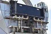 Upper aqueduct door with U-shape seal and pumping system
 -
 Locking mechanisms include securing pin at the top and hydraulic clamp at the bottom
 -
 Securing pin and clamp receptors on a caisson (1 and 2), and a wheel securing pin receptor (3)
 -
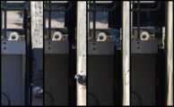 Left to right: caisson door (behind the rail) aligned with basin door but with a gap, u-shape seal extended, water filled, and doors lowered
 -
The doors being lowered at the lower canal basin


Engine room
[edit]The area housing the machinery to drive the wheel is located in the final pillar of the aqueduct, and contains seven chambers connected by ladders.[38]Access is by a door located at ground level or an entrance halfway up the tower, with agantry craneto facilitate the installation of equipment.[38]
The ground floor houses thetransformersfor powering the wheel. When the wheel was flooded by vandals in April 2002, this room was filled to within 8 cm (3 in) of the 11-kVbusbars.[38]On the first floor is a standby generator andswitchgearshould themains supplyto the wheel fail.[38]The second floor houses a pair ofhydraulic pumpsthat drive thehydraulic motorsin the chamber above.[38]Power is supplied directly to the axle with 10 hydraulic motors, which also double as brakes. Connected to each motor is a 100:1 gear system to reduce the rotation speed.[38]
Mechanism
[edit]
The caissons are required to turn with the wheel in order to remain level. Whilst the weight of the caissons on the bearings is generally sufficient to rotate them, a gearing mechanism using three large identically sized gears connected by two smaller ones ensures that they turn at precisely the correct speed and remain correctly balanced.[39]
Each end of each caisson is supported on small wheels, which run on rails on the inside face of the 8 m (26 ft) diameter holes at the ends of the arms.[39]The rotation is controlled by a train of gears: an alternating pattern of three 8 m (26 ft) diameter ring gears and two smaller idler gears, all with external teeth, as shown in the picture.[39]The large central gear is fitted loosely over the axle at its machine-room end and fixed in place to prevent it from rotating.[38][39]The two smaller gears are fixed to each of the arms of the wheel at its machine-room end. When the motors rotate the central axle, the arms swing and the small gears engage the central gear, which results in the smaller gears rotating at a higher speed than the wheel but in the same direction. The smaller gears engage the large ring gears at the end of the caissons, driving them at the same speed as the wheel but in the opposite direction. This cancels the rotation due to the arms and keeps the caissons stable and perfectly level.[39]
Docking pit
[edit]

The docking pit is adrydock-like port isolated from the lower canal basin by watertight gates and kept dry by water pumps.[20]When the wheel stops with its arms in the vertical position it is possible for boats to enter and exit the lower caisson when the gates are open without flooding the docking-pit. The space below the caisson is empty.[20][27]
Without the docking-pit, the caissons and extremities of the arms of the wheel would be immersed in water at the lower canal basin each time the wheel rotated.[20]Thebuoyancyof the lower caisson would make it more difficult to turn the wheel.[20]
Visitor centre
[edit]A visitor centre is located on the east side of the lower basin.[12]Boat trips on the wheel depart approximately once an hour.[40]Since the wheel opened, around 5.5 million people have visited[41]and 1.3 million have taken a boat trip, with around 400,000 people visiting the wheel annually.[42][43]

See also
[edit]- Anderton boat lift
- Canals of the United Kingdom
- Forth and Clyde Canal Pathway
- Lifts on the old Canal du Centre
- List of boat lifts
- Peterborough Lift Lock
- Strépy-Thieu boat lift
- The Helix (Falkirk)
References
[edit]Citations
[edit]- ^ab"History of The Falkirk Wheel".Scottish Waterways Trust. Archived fromthe originalon 7 January 2014.Retrieved6 January2013.
- ^ab"History".The Falkirk Wheel. Archived fromthe originalon 29 December 2012.Retrieved6 January2013.
- ^abc"The Millennium Link"(PDF).University of Edinburgh. Archived fromthe original(PDF)on 8 January 2014.Retrieved8 January2014.
- ^abPaterson 2013,p. 1875
- ^abPaterson 2013,p. 1877
- ^abcPaterson 2013,p. 1880
- ^abcdPaterson 2013,p. 1885
- ^Paterson 2013,pp. 1885–1886
- ^Paterson 2013,p. 1886
- ^Paterson 2013,p. 1887
- ^Paterson 2013,p. 1889
- ^abcdePaterson 2013,p. 1890
- ^abc"Civil Engineering: The Falkirk Wheel"(PDF).bacsol.co.uk. Archived fromthe original(PDF)on 14 January 2014.Retrieved14 January2014.
- ^ab"The Falkirk Ferris Wheel".gentles.info.Retrieved11 January2014.
- ^abcdefghi"Falkirk Wheel site visit – information sheet"(PDF).University of Edinburgh. Archived fromthe original(PDF)on 12 January 2014.Retrieved11 January2014.
- ^"Building the missing link".millenniumnow.org.uk. Archived fromthe originalon 6 January 2014.Retrieved11 January2014.
- ^abCrawford 2013,p. 206
- ^"Falkirk Wheel".urbanrealm.com.Retrieved7 February2014.
- ^Richard Waite (15 July 2011)."Rebrand: Paul Stallan leads RMJM rebirth".Architects' Journal.Retrieved7 February2014.
- ^abcdefgFreeland, Lee."The Falkirk Wheel"(PDF).elevator-world.com. Archived fromthe original(PDF)on 3 March 2016.Retrieved19 September2008.
- ^"British Design 1948-2012: Innovation in the Modern Age"(PDF).Victoria and Albert Museum.Retrieved11 January2014.
- ^"Banknote Design Features: Bank of Scotland Bridges Series".The Committee of Scottish Clearing Bankers.Retrieved12 January2014.
- ^abcd"Quick quirky facts".The Falkirk Wheel. Archived fromthe originalon 16 January 2014.Retrieved12 January2014.
- ^"Reinventing the Wheel".gentles.info.Retrieved13 January2014.
- ^"Design and engineering".The Falkirk Wheel. Archived fromthe originalon 30 December 2012.Retrieved6 January2013.
- ^Review of the Session.Royal Society of Edinburgh. 2003. pp. 91–92.
- ^abc"Falkirk Wheel".engineering-timelines.com. Archived fromthe originalon 13 January 2014.Retrieved13 January2014.
- ^ab"Wheel back on roll after vandalism repair work".The Scotsman.14 October 2002.Retrieved6 January2014.
- ^"Falkirk Wheel Vandalism".gentles.info.Retrieved12 January2014.
- ^"Giant rotating wheel carries boats between canals".Siviele Ingenieurswese.10:145. 2002.
- ^InCom 2009,p. 26
- ^ab"Symbol of the Millennium: The Falkirk Wheel".ASME.Retrieved12 January2014.
- ^American Society of Civil Engineers 2001,p. 48
- ^West, Timothy (2 November 2017).Our Great Canal Journeys: A Lifetime of Memories on Britain's Most Beautiful Waterways: A Lifetime of Memories on Britain's Most Beautiful Waterways.Kings Road Publishing. p. n.p.ISBN978-1-78606-862-0.
- ^"Falkirk Wheel".Institution of Civil Engineers (ICE).15 February 2018.Retrieved8 January2021.
- ^ab"Falkirk Wheel Doors and Seals".gentles.info.Retrieved13 January2014.
- ^"How it Works".Scottish Canals. Archived fromthe originalon 9 April 2018.Retrieved9 April2018.
- ^abcdefg"Falkirk Wheel Drive Chamber Visit".gentles.info.Retrieved12 January2013.
- ^abcde"How does it work?".The Falkirk Wheel. Archived fromthe originalon 8 January 2013.Retrieved12 January2013.
- ^"Opening Times".The Falkirk Wheel. Archived fromthe originalon 6 January 2014.Retrieved15 January2014.
- ^"About The Falkirk Wheel".Archived fromthe originalon 31 August 2018.Retrieved9 April2018.
- ^"Falkirk Wheel is a big success".Scottish Tourism Alliance. Archived fromthe originalon 16 January 2014.Retrieved14 January2014.
- ^"British tourist attraction visitors figures: who's up and who's down?".The Guardian.23 February 2011.Retrieved14 January2014.
Sources
[edit]- Crawford, Robert (2013).On Glasgow and Edinburgh.Harvard University Press.ISBN9780674070592.
- InCom (2009).Innovations in Navigation Lock Design.PIANC.ISBN9782872231751.
- Paterson, Len (2013).From Sea to Sea: A History of the Scottish Lowland and Highland Canals.Neil Wilson Publishing.ISBN9781906000349.
- American Society of Civil Engineers (2001).International engineering history and heritage: Improving bridges to ASCE's 150th anniversary: Proceedings of the third National Congress on Civil Engineering History and Heritage.American Society of Civil Engineers.ISBN9780784405949.
External links
[edit]| International | |
|---|---|
| Geographic | |