Caustics produced by a glass of water, visible as patches of lightNephroidcaustic at the bottom of a teacupCaustics made by the surface of waterCaustics in shallow water
Inoptics,acausticorcaustic network[1]is theenvelopeoflight rayswhich have beenreflectedorrefractedby a curved surface or object, or theprojectionof that envelope of rays on another surface.[2]The caustic is acurveorsurfaceto which each of the light rays istangent,defining a boundary of an envelope of rays as a curve of concentrated light.[2]In some cases caustics can be seen as patches of light or their bright edges, shapes which often havecusp singularities.
The rays refracted by a non-flat surface form caustics where many of them cross.
Concentration of light, especiallysunlight,can burn. The wordcaustic,in fact, comes from the Greek καυστός, burnt, via the Latincausticus,burning.
A common situation where caustics are visible is when light shines on a drinking glass. The glass casts a shadow, but also produces a curved region of bright light. In ideal circumstances (including perfectly parallel rays, as if from a point source at infinity), anephroid-shaped patch of light can be produced.[3][4]Rippling caustics are commonly formed when light shines through waves on a body of water.
Another familiar caustic is therainbow.[5][6]Scattering of light by raindrops causes differentwavelengthsof light to be refracted into arcs of differing radius, producing the bow.
Photograph of a typical wine glass causticComputer rendering of a wine glass caustic
In computer graphics, most modernrendering systemssupport caustics. Some of them even supportvolumetriccaustics. This is accomplished byraytracingthe possible paths of a light beam, accounting for the refraction and reflection.Photon mappingis one implementation of this. Volumetric caustics can also be achieved byvolumetric path tracing.Some computer graphic systems work by "forward ray tracing" wherein photons are modeled as coming from a light source and bouncing around the environment according to rules. Caustics are formed in the regions where sufficient photons strike a surface causing it to be brighter than the average area in the scene. “Backward ray tracing” works in the reverse manner beginning at the surface and determining if there is a direct path to the light source.[7]Some examples of 3D ray-traced caustics can be foundhere.
The focus of most computer graphics systems is aesthetics rather thanphysical accuracy.This is especially true when it comes to real-time graphics in computer games[8]where generic pre-calculatedtexturesare mostly used instead of physically correct calculations.
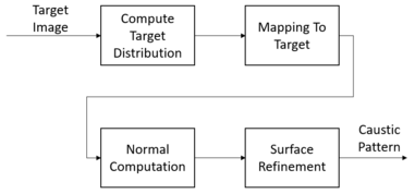
Caustic engineering describes the process of solving theinverse problemtocomputer graphics.That is, given a specific image, to determine a surface whose refracted or reflected light forms this image.
In the discrete version of this problem, the surface is divided into several micro-surfaces which are assumed smooth, i.e. the light reflected/refracted by each micro-surface forms a Gaussian caustic. Gaussian caustic means that each micro-surface obeyGaussian distribution.The position and orientation of each of the micro-surfaces are then obtained using a combination ofPoisson integrationandsimulated annealing.[9]
There have been many different approaches to address the continuous problem. One approach uses an idea fromtransportation theorycalledoptimal transport[10]to find a mapping between incoming light rays and the target surface. After obtaining such a mapping, the surface is optimized by adapting it iteratively usingSnell's lawof refraction.[11][12]
Controlling caustic pattern is rather a challenging problem as very minor changes of the surface will significantly affect the quality of the pattern since light ray directions might be interfered by other light rays as they intersect with and refract through the material. This will lead to a scattered, discontinuous pattern. To tackle this problem, optimal-transport-based is one of the existing proposed methods to control caustic pattern by redirecting light's directions as it propagates through the surface of a certaintransparent material.This is done by solving an inverse optimization problem based onoptimal transport.[13][14]Given a reference image of an object/pattern, the target is to formulate the mathematical description of the material surface through which light refracts and converges to the similar pattern of the reference image. This is done by rearranging/recomputing the initial light intensity until the minimum of the optimization problem is reached.
Here considering only refractive caustic, the objective can be determined as follows (similar principle for reflective caustic with different output):
Input:image of pattern to be obtained after propagating lights through the material, given the light source position.
Output:caustic geometry on the receiver (flat solid surface, e.g.: floor, wall, etc...)
In order to achieve the target pattern, the surface where light refracts through and exits to the outer environment must be manufactured into certain shape to achieve desired pattern on the other side of the material.
As mentioned, given an input image, this process will produce the similar caustic pattern as the output. In principle, there are two core stages with each includes two sub-stages:
Optimal-transport-based caustic designSolving Optimal Transport Problem
Compute Target Light Distribution
Compute Mapping from Initial Distribution to Target Distribution
As the case refraction occurs through a transparent surface, for instance the patterns appearing under clear water surface, 3 main phenomena can be observed:
Very bright (condensed light intensity) points (so-calledsingularity)
Curve-like objects that connect the points
Regions with low light intensity
To perform computation, the following 3 quantities are being respectively introduced to describe the geometric characteristics of the pattern: point singularity(measuring light intensity at certain highly concentrated light-point), curve singularity(measuring light intensity at/around a light-curve), andirradiance measure(measuring intensity in a certain poorly concentrated light-area). Putting them altogether, the following function defines the totalradiant flux measureat a certain section Ω on the target surface:
After this step, there are two existing measures of the radiant flux measures of the source(uniform distribution, by initialization) and the target(computed in previous step). What remains to compute is the mapping from the source to target. In order to do this, there are several quantities to be defined. Firstly, two light intensities evaluated by probabilities:(light intensity evaluated by dividingby thefluxof the union region betweenand),(light intensity evaluated by dividingby thefluxof the union region betweenand) are defined. Secondly, the source mesh is generated as multiple sites,which is later being deformed. Next, apower diagram(a set ofpower cells) is defined on this set of sitesweighted by a weight vector.Finally, the goal is to decide whether which power cells are going to be move. Considering allvertices on the surface, finding the minimizerof the followingconvex functionwill produce the matched power diagram for the target:
After solving optimal transport problem, the vertices are achieved. However, this gives no information about what the final surface should look like. To achieve the desired target surface given the incoming light ray,outgoing light rayand power diagram from the step above, the surface normals representation can be computed according toSnell's lawas:
:target position obtained from solving above optimal transport problem
As the normal representation is obtained, surface refinement is then achieved by minimizing the followingcompound energy function:
where,
is the integration energy that aligns the vertex normalsobtained from the Optimal Transport with the target normalsobtained from the Snell's law computation above.
as mesh generated in step Solving Optimal Transport cannot adapt to the sharp instances from the discontinuities, this energy is to penalize the vertices to not change significantly from the incoming light ray.
is the energy measuring the flux over the trianglein the mesh.
is the energy that regularizes the shape of the triangles to maintain its well-shapedness.
is barrier energy to ensure that surface does not deform beyond a certain distance threshold.
Inverse graphicsis a method of observing the data from an image and inferring all possible properties including 3D geometry, lighting, materials, and motion in order to generate a realistic image.[15]In conventional computer graphics, to render an image with desired appearance and effects, it is given all the relevant properties/characteristics. This could be described as the forward method. On the contrary, in caustic design, the properties and characteristics of objects (especially the material surface) are not trivial. The given constraint is the target image to obtain. Therefore, the goal is to obtain its properties and characteristics by observing and inferring the target image. This can be considered the inverse/backward method.
The following is the basicloss functionexplaining how to optimize the parameters:
where,
L(c):loss function, mean square error of the rendered image and the target
c:contains elements which can influence the generated image
At first, the target pattern is designed and the forward pass computed to get the synthetic pattern. It's compared to the target pattern and get the loss.
The objection is to let the synthetic pattern is similar to the target pattern as much as possible. And then do the back propagation to get the optimized properties need to use in caustic manufacturing.
Introduce U as an intermediate variable indicating 2D projected vertex coordinate positions. The gradient of these properties can be derived by chain rule indirectly.
After applying thestochastic gradient descent,the optimal,andcould be achieved. Subsequently, these quantities are used to carve or mill the material to generate the target pattern.
One common approach is to utilize the ability to perform differential operations in variousdeep learningauto-differentiation frameworks/libraries such as:Tensorflow,PyTorch,Theano.
One more approach is to make use of the OpenDR[16]framework to build a forward graphics model and to automatically obtain derivatives with respect to the model parameters for optimization. As optimization properties are obtained, the target image can be generated. OpenDR provides a local optimization method that can be incorporated into probabilistic programming frameworks. This can be used to solve the problem of caustic.
Once the caustic pattern has been designed computationally, the processed data will be then sent to the manufacturing stage to get the final product. The most common approach issubtractive manufacturing(machining).
Various materials can be used depending on the desired quality, the effort it takes to manufacture, and the available manufacturing method.
^Loper, Matthew M.; Black, Michael J. (2014), "OpenDR: An Approximate Differentiable Renderer",Computer Vision – ECCV 2014,Springer International Publishing, pp. 154–169,doi:10.1007/978-3-319-10584-0_11,ISBN978-3-319-10583-3
^Loper, Matthew M.; Black, Michael J. (2014), "OpenDR: An Approximate Differentiable Renderer",Computer Vision – ECCV 2014,Springer International Publishing, pp. 154–169,doi:10.1007/978-3-319-10584-0_11,ISBN978-3-319-10583-3
Dachsbacher, Carsten; Liktor, Gábor (February 2011). "Real-time volume caustics with adaptive beam tracing".Symposium on Interactive 3D Graphics and Games.ACM: 47–54.


![{\displaystyle {\underset {x}{\operatorname {arg\,max} }}\,\omega \,\cdot [E_{int},\,E_{dir},\,E_{flux},\,E_{reg},\,E_{bar}]}](https://wikimedia.org/api/rest_v1/media/math/render/svg/1d94eb1a2815651606db3307362526d05a207426)


