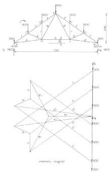
Cremona diagram
This articleneeds additional citations forverification.(October 2016) |

TheCremona diagram,also known as the Cremona-Maxwellmethod, is a graphical method used instaticsoftrussesto determine the forces in members (graphic statics). The method was developed by the Italian mathematicianLuigi Cremona.However, recognizable Cremona diagrams appeared as early as 1725, inPierre Varignon's posthumously published work,Nouvelle Méchanique ou Statique.[1]
In the Cremona method, first the external forces and reactions are drawn (toscale) forming a vertical line in the lower right side of the picture. This is thesumof all the forcevectorsand is equal to zero as there ismechanical equilibrium.
Since the equilibrium holds for the external forces on the entire truss construction, it also holds for the internal forces acting on each joint. For a joint to beat restthe sum of the forces on a joint must also be equal to zero. Starting at jointAorda,the internal forces can be found by drawing lines in the Cremona diagram representing the forces in the members 1 and 4, going clockwise;VA(going up) load atA(going down), force in member 1 (going down/left), member 4 (going up/right) and closing withVA.As the force in member 1 is towards the joint, the member is under compression, the force in member 4 is away from the joint so the member 4 is under tension. The length of the lines for members 1 and 4 in the diagram, multiplied with the chosen scalefactoris themagnitudeof the force in members 1 and 4.
Now, in the same way the forces in members 2 and 6 can be found for jointC;force in member 1 (going up/right), force inCgoing down, force in 2 (going down/left), force in 6 (going up/left) and closing with the force in member 1.
The same steps can be taken for jointsD,HandEresulting in the complete Cremona diagram where the internal forces in all members are known.
In a next phase the forces caused bywindmust be considered. Wind will cause pressure on the upwind side of aroof(and truss) and suction on the downwind side. This will translate to asymmetrical loads but the Cremona method is the same. Wind force may introduce larger forces in the individual truss members than the static vertical loads.
References
[edit]- ^Rippmann, Matthias (2016),Funicular Shell Design: Geometric Approaches to Form Finding and Fabrication of Discrete Funicular Structures,Habilitationthesis, Diss. ETH No. 23307,ETH Zurich,pp. 39–40,doi:10.3929/ethz-a-010656780.See alsoErickson, Jeff (June 9, 2016),Reciprocal force diagrams fromNouvelle Mécanique ou Statiqueby Pierre de Varignon (1725).
