
Electric power transmission
This article has multiple issues.Please helpimprove itor discuss these issues on thetalk page.(Learn how and when to remove these template messages)
|

Electric power transmissionis the bulk movement ofelectrical energyfrom ageneratingsite, such as apower plant,to anelectrical substation.The interconnected lines that facilitate this movement form atransmission network.This is distinct from the local wiring between high-voltage substations and customers, which is typically referred to aselectric power distribution.The combined transmission and distribution network is part ofelectricity delivery,known as theelectrical grid.
Efficient long-distance transmission of electric power requires highvoltages.This reduces the losses produced by strongcurrents.Transmission lines use eitheralternating current(AC) ordirect current(DC). The voltage level is changed withtransformers.The voltage is stepped up for transmission, then reduced for local distribution.
Awide area synchronous grid,known as aninterconnectionin North America, directly connects generators delivering AC power with the same relativefrequencyto many consumers. North America has four major interconnections:Western,Eastern,QuebecandTexas.One grid connects most of continental Europe.
Historically, transmission and distribution lines were often owned by the same company, but starting in the 1990s, many countriesliberalizedthe regulation of theelectricity marketin ways that led to separate companies handling transmission and distribution.[2]
System
[edit]
Most North American transmission lines are high-voltagethree-phaseAC, althoughsingle phaseAC is sometimes used inrailway electrification systems.DC technology is used for greater efficiency over longer distances, typically hundreds of miles.High-voltage direct current(HVDC) technology is also used insubmarine power cables(typically longer than 30 miles (50 km)), and in the interchange of power between grids that are not mutually synchronized. HVDC links stabilize power distribution networks where sudden new loads, or blackouts, in one part of a network might otherwise result in synchronization problems andcascading failures.
Electricity is transmitted athigh voltagesto reduce the energy loss due toresistancethat occurs over long distances. Power is usually transmitted throughoverhead power lines.Underground power transmissionhas a significantly higher installation cost and greater operational limitations, but lowers maintenance costs. Underground transmission is more common in urban areas or environmentally sensitive locations.
Electrical energy must typically be generated at the same rate at which it is consumed. A sophisticated control system is required to ensure thatpower generationclosely matches demand. If demand exceeds supply, the imbalance can cause generation plant(s) and transmission equipment to automatically disconnect or shut down to prevent damage. In the worst case, this may lead to a cascading series of shutdowns and a major regionalblackout.
The US Northeast faced blackouts in1965,1977,2003,and major blackouts in other US regions in1996and2011.Electric transmission networks are interconnected into regional, national, and even continent-wide networks to reduce the risk of such a failure by providing multipleredundant,alternative routes for power to flow should such shutdowns occur. Transmission companies determine the maximum reliable capacity of each line (ordinarily less than its physical or thermal limit) to ensure that spare capacity is available in the event of a failure in another part of the network.
Overhead
[edit]

High-voltage overhead conductors are not covered by insulation. The conductor material is nearly always analuminumalloy, formed of several strands and possibly reinforced with steel strands. Copper was sometimes used for overhead transmission, but aluminum is lighter, reduces yields only marginally and costs much less. Overhead conductors are supplied by several companies. Conductor material and shapes are regularly improved to increase capacity.
Conductor sizes range from 12 mm2(#6American wire gauge) to 750 mm2(1,590,000circular milsarea), with varying resistance andcurrent-carrying capacity.For large conductors (more than a few centimetres in diameter), much of the current flow is concentrated near the surface due to theskin effect.The center of the conductor carries little current but contributes weight and cost. Thus, multiple parallel cables (calledbundle conductors) are used for higher capacity. Bundle conductors are used at high voltages to reduce energy loss caused bycorona discharge.
Today, transmission-level voltages are usually 110 kV and above. Lower voltages, such as 66 kV and 33 kV, are usually consideredsubtransmissionvoltages, but are occasionally used on long lines with light loads. Voltages less than 33 kV are usually used fordistribution.Voltages above 765 kV are consideredextra high voltageand require different designs.
Overhead transmission wires depend on air for insulation, requiring that lines maintain minimum clearances. Adverse weather conditions, such as high winds and low temperatures, interrupt transmission. Wind speeds as low as 23 knots (43 km/h) can permit conductors to encroach operating clearances, resulting in aflashoverand loss of supply.[3]Oscillatory motion of the physical line is termedconductor gallop or flutterdepending on the frequency and amplitude of oscillation.
-
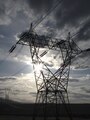 A five-hundred kilovolt (500 kV) three-phase transmission tower in Washington State, the line is bundled 3-ways
 -
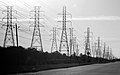 Three abreast electrical pylons in Webster, Texas

Underground
[edit]Electric power can be transmitted byunderground power cables.Underground cables take up no right-of-way, have lower visibility, and are less affected by weather. However, cables must be insulated. Cable and excavation costs are much higher than overhead construction. Faults in buried transmission lines take longer to locate and repair.
In some metropolitan areas, cables are enclosed by metal pipe and insulated withdielectric fluid(usually an oil) that is either static or circulated via pumps. If an electric fault damages the pipe and leaks dielectric, liquid nitrogen is used to freeze portions of the pipe to enable draining and repair. This extends the repair period and increases costs. The temperature of the pipe and surroundings are monitored throughout the repair period.[4][5][6]
Underground lines are limited by their thermal capacity, which permits less overload or re-rating lines. Long underground AC cables have significantcapacitance,which reduces their ability to provide useful power beyond 50 miles (80 kilometres). DC cables are not limited in length by their capacitance.
History
[edit]
Commercial electric power was initially transmitted at the same voltage used by lighting and mechanical loads. This restricted the distance between generating plant and loads. In 1882, DC voltage could not easily be increased for long-distance transmission. Different classes of loads (for example, lighting, fixed motors, and traction/railway systems) required different voltages, and so used different generators and circuits.[7][8]
Thus, generators were sited near their loads, a practice that later became known asdistributed generationusing large numbers of small generators.[9]
Transmission ofalternating current(AC) became possible afterLucien GaulardandJohn Dixon Gibbsbuilt what they called the secondary generator, an earlytransformerprovided with 1:1 turn ratio and open magnetic circuit, in 1881.
The first long distance AC line was 34 kilometres (21 miles) long, built for the 1884 International Exhibition of Electricity inTurin, Italy.It was powered by a 2 kV, 130 HzSiemens & Halskealternator and featured several Gaulard transformers with primary windings connected in series, which fed incandescent lamps. The system proved the feasibility of AC electric power transmission over long distances.[8]
The first commercial AC distribution system entered service in 1885 in via dei Cerchi,Rome, Italy,for public lighting. It was powered by two Siemens & Halske alternators rated 30 hp (22 kW), 2 kV at 120 Hz and used 19 km of cables and 200 parallel-connected 2 kV to 20 V step-down transformers provided with a closed magnetic circuit, one for each lamp. A few months later it was followed by the first British AC system, servingGrosvenor Gallery.It also featured Siemens alternators and 2.4 kV to 100 V step-down transformers – one per user – with shunt-connected primaries.[10]
Working to improve what he considered an impractical Gaulard-Gibbs design, electrical engineerWilliam Stanley, Jr.developed the first practical series AC transformer in 1885.[11]Working with the support ofGeorge Westinghouse,in 1886 he demonstrated a transformer-based AC lighting system inGreat Barrington, Massachusetts.It was powered by a steam engine-driven 500 V Siemens generator. Voltage was stepped down to 100 volts using the Stanley transformer to power incandescent lamps at 23 businesses over 4,000 feet (1,200 m).[12]This practical demonstration of a transformer and alternating current lighting system led Westinghouse to begin installing AC systems later that year.[11]
In 1888 the first designs for anAC motorappeared. These wereinduction motorsrunning onpolyphasecurrent, independently invented byGalileo FerrarisandNikola Tesla.Westinghouse licensed Tesla's design. Practicalthree-phasemotors were designed byMikhail Dolivo-DobrovolskyandCharles Eugene Lancelot Brown.[13]Widespread use of such motors were delayed many years by development problems and the scarcity ofpolyphase power systemsneeded to power them.[14][15]

In the late 1880s and early 1890s smaller electric companies merged into larger corporations such asGanzandAEGin Europe andGeneral ElectricandWestinghouse Electricin the US. These companies developed AC systems, but the technical difference between direct and alternating current systems required a much longer technical merger.[16]Alternating current's economies of scale with large generating plants and long-distance transmission slowly added the ability to link all the loads. These included single phase AC systems, poly-phase AC systems, low voltage incandescent lighting, high-voltage arc lighting, and existing DC motors in factories and street cars. In what became a universal system, these technological differences were temporarily bridged via therotary convertersandmotor-generatorsthat allowed the legacy systems to connect to the AC grid.[16][17]These stopgaps were slowly replaced as older systems were retired or upgraded.
The first transmission of single-phase alternating current using high voltage came in Oregon in 1890 when power was delivered from a hydroelectric plant atWillamette Fallsto the city ofPortland14 miles (23 km) down river.[18]The first three-phase alternating current using high voltage took place in 1891 during theinternational electricity exhibitioninFrankfurt.A 15 kV transmission line, approximately 175 km long, connectedLauffen on the Neckarand Frankfurt.[10][19]
Transmission voltages increased throughout the 20th century. By 1914, fifty-five transmission systems operating at more than 70 kV were in service. The highest voltage then used was 150 kV.[20]Interconnecting multiple generating plants over a wide area reduced costs. The most efficient plants could be used to supply varying loads during the day. Reliability was improved and capital costs were reduced, because stand-by generating capacity could be shared over many more customers and a wider area. Remote and low-cost sources of energy, such ashydroelectricpower or mine-mouth coal, could be exploited to further lower costs.[7][10]
The 20th century's rapid industrialization made electrical transmission lines and gridscritical infrastructure.Interconnection of local generation plants and small distribution networks was spurred byWorld War I,when large electrical generating plants were built by governments to power munitions factories.[21]
Bulk transmission
[edit]
These networks use components such as power lines, cables,circuit breakers,switches andtransformers.The transmission network is usually administered on a regional basis by an entity such as aregional transmission organizationortransmission system operator.[22]
Transmission efficiency is improved at higher voltage and lower current. The reduced current reduces heating losses.Joule's first lawstates that energy losses are proportional to the square of the current. Thus, reducing the current by a factor of two lowers the energy lost to conductor resistance by a factor of four for any given size of conductor.
The optimum size of a conductor for a given voltage and current can be estimated by Kelvin's law for conductor size, which states that size is optimal when the annual cost of energy wasted in resistance is equal to the annual capital charges of providing the conductor. At times of lower interest rates and low commodity costs, Kelvin's law indicates that thicker wires are optimal. Otherwise, thinner conductors are indicated. Since power lines are designed for long-term use, Kelvin's law is used in conjunction with long-term estimates of the price of copper and aluminum as well as interest rates.
Higher voltage is achieved in AC circuits by using astep-uptransformer.High-voltage direct current(HVDC) systems require relatively costly conversion equipment that may be economically justified for particular projects such as submarine cables and longer distance high capacity point-to-point transmission. HVDC is necessary for sending energy between unsynchronized grids.
A transmission grid is a network ofpower stations,transmission lines, andsubstations.Energy is usually transmitted within a grid withthree-phaseAC.Single-phase AC is used only for distribution to end users since it is not usable for large polyphaseinduction motors.In the 19th century, two-phase transmission was used but required either four wires or three wires with unequal currents. Higher order phase systems require more than three wires, but deliver little or no benefit.

While the price of generating capacity is high, energy demand is variable, making it often cheaper to import needed power than to generate it locally. Because loads often rise and fall together across large areas, power often comes from distant sources. Because of the economic benefits of load sharing,wide area transmission gridsmay span countries and even continents. Interconnections between producers and consumers enables power to flow even if some links are inoperative.
The slowly varying portion of demand is known as thebase loadand is generally served by large facilities with constant operating costs, termedfirm power.Such facilities are nuclear, coal or hydroelectric, while other energy sources such asconcentrated solar thermalandgeothermal powerhave the potential to provide firm power. Renewable energy sources, such as solar photovoltaics, wind, wave, and tidal, are, due to their intermittency, not considered to be firm. The remaining orpeakpower demand, is supplied bypeaking power plants,which are typically smaller, faster-responding, and higher cost sources, such ascombined cycleor combustion turbine plants typically fueled by natural gas.
Long-distance transmission (hundreds of kilometers) is cheap and efficient, with costs of US$0.005–0.02 per kWh, compared to annual averaged large producer costs of US$0.01–0.025 per kWh, retail rates upwards of US$0.10 per kWh, and multiples of retail for instantaneous suppliers at unpredicted high demand moments.[23]New York often buys over 1000 MW of low-cost hydropower from Canada.[24]Local sources (even if more expensive and infrequently used) can protect the power supply from weather and other disasters that can disconnect distant suppliers.

Hydro and wind sources cannot be moved closer to big cities, and solar costs are lowest in remote areas where local power needs are nominal. Connection costs can determine whether any particular renewable alternative is economically realistic. Costs can be prohibitive for transmission lines, but high capacity, long distancesuper gridtransmission network costs could be recovered with modest usage fees.
Grid input
[edit]Atpower stations,power is produced at a relatively low voltage between about 2.3 kV and 30 kV, depending on the size of the unit. The voltage is then stepped up by the power stationtransformerto a higher voltage (115 kV to 765 kV AC) for transmission.
In the United States, power transmission is, variously, 230 kV to 500 kV, with less than 230 kV or more than 500 kV as exceptions.
TheWestern Interconnectionhas two primary interchange voltages: 500 kV AC at 60 Hz, and ±500 kV (1,000 kV net) DC from North to South (Columbia RivertoSouthern California) and Northeast to Southwest (Utah to Southern California). The 287.5 kV (Hoover DamtoLos Angelesline, viaVictorville) and 345 kV (Arizona Public Service(APS) line) are local standards, both of which were implemented before 500 kV became practical.
Losses
[edit]Transmitting electricity at high voltage reduces the fraction of energy lost toJoule heating,which varies by conductor type, the current, and the transmission distance. For example, a 100 mi (160 km) span at 765 kV carrying 1000 MW of power can have losses of 0.5% to 1.1%. A 345 kV line carrying the same load across the same distance has losses of 4.2%.[25]For a given amount of power, a higher voltage reduces the current and thus theresistive losses.For example, raising the voltage by a factor of 10 reduces the current by a corresponding factor of 10 and therefore thelosses by a factor of 100, provided the same sized conductors are used in both cases. Even if the conductor size (cross-sectional area) is decreased ten-fold to match the lower current, thelosses are still reduced ten-fold using the higher voltage.

While power loss can also be reduced by increasing the wire'sconductance(by increasing its cross-sectional area), larger conductors are heavier and more expensive. And since conductance is proportional to cross-sectional area, resistive power loss is only reduced proportionally with increasing cross-sectional area, providing a much smaller benefit than the squared reduction provided by multiplying the voltage.
Long-distance transmission is typically done with overhead lines at voltages of 115 to 1,200 kV. At higher voltages, where more than 2,000 kV exists between conductor and ground,corona dischargelosses are so large that they can offset the lower resistive losses in the line conductors. Measures to reduce corona losses include larger conductor diameter, hollow cores[26]or conductor bundles.
Factors that affect resistance and thus loss include temperature, spiraling, and theskin effect.Resistance increases with temperature. Spiraling, which refers to the way stranded conductors spiral about the center, also contributes to increases in conductor resistance. The skin effect causes the effective resistance to increase at higher AC frequencies. Corona and resistive losses can be estimated using a mathematical model.[27]
US transmission and distribution losses were estimated at 6.6% in 1997,[28]6.5% in 2007[28]and 5% from 2013 to 2019.[29]In general, losses are estimated from the discrepancy between power produced (as reported by power plants) and power sold; the difference constitutes transmission and distribution losses, assuming no utility theft occurs.
As of 1980, the longest cost-effective distance for DC transmission was 7,000 kilometres (4,300 miles). For AC it was 4,000 kilometres (2,500 miles), though US transmission lines are substantially shorter.[23]
In any AC line, conductorinductanceandcapacitancecan be significant. Currents that flow solely in reaction to these properties, (which together with theresistancedefine theimpedance) constitutereactive powerflow, which transmits no power to the load. These reactive currents, however, cause extra heating losses. The ratio of real power transmitted to the load to apparent power (the product of a circuit's voltage and current, without reference to phase angle) is thepower factor.As reactive current increases, reactive power increases and power factor decreases.
For transmission systems with low power factor, losses are higher than for systems with high power factor. Utilities add capacitor banks, reactors and other components (such asphase-shifters;static VAR compensators;andflexible AC transmission systems,FACTS) throughout the system help to compensate for the reactive power flow, reduce the losses in power transmission and stabilize system voltages. These measures are collectively called 'reactive support'.
Transposition
[edit]Current flowing through transmission lines induces amagnetic fieldthat surrounds the lines of each phase and affects theinductanceof the surrounding conductors of other phases. The conductors' mutual inductance is partially dependent on the physical orientation of the lines with respect to each other. Three-phase lines are conventionally strung with phases separated vertically. The mutual inductance seen by a conductor of the phase in the middle of the other two phases is different from the inductance seen on the top/bottom.
Unbalanced inductance among the three conductors is problematic because it may force the middle line to carry a disproportionate amount of the total power transmitted. Similarly, an unbalanced load may occur if one line is consistently closest to the ground and operates at a lower impedance. Because of this phenomenon, conductors must be periodically transposed along the line so that each phase sees equal time in each relative position to balance out the mutual inductance seen by all three phases. To accomplish this, line position is swapped at specially designedtransposition towersat regular intervals along the line using varioustransposition schemes.
Subtransmission
[edit]

Subtransmission runs at relatively lower voltages. It is uneconomical to connect alldistribution substationsto the high main transmission voltage, because that equipment is larger and more expensive. Typically, only larger substations connect with this high voltage. Voltage is stepped down before the current is sent to smaller substations. Subtransmission circuits are usually arranged in loops so that a single line failure does not stop service to many customers for more than a short time.
Loops can benormally closed,where loss of one circuit should result in no interruption, ornormally openwhere substations can switch to a backup supply. While subtransmission circuits are usually carried onoverhead lines,in urban areas buried cable may be used. The lower-voltage subtransmission lines use less right-of-way and simpler structures; undergrounding is less difficult.
No fixed cutoff separates subtransmission and transmission, or subtransmission anddistribution.Their voltage ranges overlap. Voltages of 69 kV, 115 kV, and 138 kV are often used for subtransmission in North America. As power systems evolved, voltages formerly used for transmission were used for subtransmission, and subtransmission voltages became distribution voltages. Like transmission, subtransmission moves relatively large amounts of power, and like distribution, subtransmission covers an area instead of just point-to-point.[30]
Transmission grid exit
[edit]Substationtransformers reduce the voltage to a lower level fordistributionto customers. This distribution is accomplished with a combination of sub-transmission (33 to 138 kV) and distribution (3.3 to 25 kV). Finally, at the point of use, the energy is transformed to end-user voltage (100 to 4160 volts).
Advantage of high-voltage transmission
[edit]High-voltage power transmission allows for lesser resistive losses over long distances. This efficiency delivers a larger proportion of the generated power to the loads.


In a simplified model, the grid delivers electricity from anideal voltage sourcewith voltage,delivering a power) to a single point of consumption, modelled by a resistance,when the wires are long enough to have a significant resistance.


If the resistances arein serieswith no intervening transformer, the circuit acts as avoltage divider,because the same currentruns through the wire resistance and the powered device. As a consequence, the useful power (at the point of consumption) is:


Should anideal transformerconvert high-voltage, low-current electricity into low-voltage, high-current electricity with a voltage ratio of(i.e., the voltage is divided byand the current is multiplied byin the secondary branch, compared to the primary branch), then the circuit is again equivalent to a voltage divider, but the wires now have apparent resistance of only.The useful power is then:


For(i.e. conversion of high voltage to low voltage near the consumption point), a larger fraction of the generator's power is transmitted to the consumption point and a lesser fraction is lost toJoule heating.

Modeling
[edit]
The terminal characteristics of the transmission line are the voltage and current at the sending (S) and receiving (R) ends. The transmission line can be modeled as ablack boxand a 2 by 2 transmission matrix is used to model its behavior, as follows:

The line is assumed to be a reciprocal, symmetrical network, meaning that the receiving and sending labels can be switched with no consequence. The transmission matrixThas the properties:


The parametersA,B,C,andDdiffer depending on how the desired model handles the line'sresistance(R),inductance(L),capacitance(C), and shunt (parallel, leak)conductanceG.
The four main models are the short line approximation, the medium line approximation, the long line approximation (with distributed parameters), and the lossless line. In such models, a capital letter such asRrefers to the total quantity summed over the line and a lowercase letter such ascrefers to the per-unit-length quantity.
Lossless line
[edit]The lossless line approximation is the least accurate; it is typically used on short lines where the inductance is much greater than the resistance. For this approximation, the voltage and current are identical at the sending and receiving ends.

The characteristic impedance is pure real, which means resistive for that impedance, and it is often called surge impedance. When a lossless line is terminated by surge impedance, the voltage does not drop. Though the phase angles of voltage and current are rotated, the magnitudes of voltage and current remain constant along the line. For load > SIL, the voltage drops from sending end and the lineconsumesVARs. For load < SIL, the voltage increases from the sending end, and the linegeneratesVARs.
Short line
[edit]The short line approximation is normally used for lines shorter than 80 km (50 mi). There, only a series impedanceZis considered, whileCandGare ignored. The final result is that A = D = 1 per unit, B = Z Ohms, and C = 0. The associated transition matrix for this approximation is therefore:

Medium line
[edit]The medium line approximation is used for lines running between 80 and 250 km (50 and 155 mi). The series impedance and the shunt (current leak) conductance are considered, placing half of the shunt conductance at each end of the line. This circuit is often referred to as anominalπ(pi)circuit because of the shape (π) that is taken on when leak conductance is placed on both sides of the circuit diagram. The analysis of the medium line produces:

Counterintuitive behaviors of medium-length transmission lines:
- voltage rise at no load or small current (Ferranti effect)
- receiving-end current can exceed sending-end current
Long line
[edit]The long line model is used when a higher degree of accuracy is needed or when the line under consideration is more than 250 km (160 mi) long. Series resistance and shunt conductance are considered to be distributed parameters, such that each differential length of the line has a corresponding differential series impedance and shunt admittance. The following result can be applied at any point along the transmission line, whereis thepropagation constant.

![{\displaystyle {\begin{aligned}A&=D=\cosh(\gamma x){\text{ per unit}}\\[3mm]B&=Z_{c}\sinh(\gamma x)\Omega \\[2mm]C&={\frac {1}{Z_{c}}}\sinh(\gamma x)S\end{aligned}}}](https://wikimedia.org/api/rest_v1/media/math/render/svg/f28171aeaaf93573b4ca8976c9ea1622d6807728)
To find the voltage and current at the end of the long line,should be replaced with(the line length) in all parameters of the transmission matrix. This model applies theTelegrapher's equations.


High-voltage direct current
[edit]High-voltage direct current (HVDC) is used to transmit large amounts of power over long distances or for interconnections between asynchronous grids. When electrical energy is transmitted over very long distances, the power lost in AC transmission becomes appreciable and it is less expensive to use direct current instead. For a long transmission line, these lower losses (and reduced construction cost of a DC line) can offset the cost of the required converter stations at each end.
HVDC is used for longsubmarine cableswhere AC cannot be used because of cable capacitance.[31]In these cases specialhigh-voltage cablesare used. Submarine HVDC systems are often used to interconnect the electricity grids of islands, for example, betweenGreat Britainandcontinental Europe,between Great Britain and Ireland, betweenTasmaniaand the Australian mainland, between the North and South Islands of New Zealand, betweenNew JerseyandNew York City,and between New Jersey andLong Island.Submarine connections up to 600 kilometres (370 mi) in length have been deployed.[32]
HVDC links can be used to control grid problems. The power transmitted by an AC line increases as thephase anglebetween source end voltage and destination ends increases, but too large a phase angle allows the systems at either end to fall out of step. Since the power flow in a DC link is controlled independently of the phases of the AC networks that it connects, this phase angle limit does not exist, and a DC link is always able to transfer its full rated power. A DC link therefore stabilizes the AC grid at either end, since power flow and phase angle can then be controlled independently.
As an example, to adjust the flow of AC power on a hypothetical line betweenSeattleandBostonwould require adjustment of the relative phase of the two regional electrical grids. This is an everyday occurrence in AC systems, but one that can become disrupted when AC system components fail and place unexpected loads on the grid. With an HVDC line instead, such an interconnection would:
- Convert AC in Seattle into HVDC;
- Use HVDC for the 3,000 miles (4,800 km) of cross-country transmission; and
- Convert the HVDC to locally synchronized AC in Boston,
(and possibly in other cooperating cities along the transmission route). Such a system could be less prone to failure if parts of it were suddenly shut down. One example of a long DC transmission line is thePacific DC Intertielocated in the Western United States.
Capacity
[edit]The amount of power that can be sent over a transmission line varies with the length of the line. The heating of short line conductors due to line losses sets a thermal limit. If too much current is drawn, conductors may sag too close to the ground, or conductors and equipment may overheat. For intermediate-length lines on the order of 100 kilometres (62 miles), the limit is set by thevoltage dropin the line. For longer AC lines,system stabilitybecomes the limiting factor. Approximately, the power flowing over an AC line is proportional to the cosine of the phase angle of the voltage and current at the ends.
This angle varies depending on system loading. It is undesirable for the angle to approach 90 degrees, as the power flowing decreases while resistive losses remain. The product of line length and maximum load is approximately proportional to the square of the system voltage. Series capacitors or phase-shifting transformers are used on long lines to improve stability. HVDC lines are restricted only by thermal and voltage drop limits, since the phase angle is not material.
Understanding the temperature distribution along the cable route became possible with the introduction ofdistributed temperature sensing(DTS) systems that measure temperatures all along the cable. Without them maximum current was typically set as a compromise between understanding of operation conditions and risk minimization. This monitoring solution uses passiveoptical fibersas temperature sensors, either inside a high-voltage cable or externally mounted on the cable insulation.
For overhead cables the fiber is integrated into the core of a phase wire. The integrated Dynamic Cable Rating (DCR)/Real Time Thermal Rating (RTTR) solution makes it possible to run the network to its maximum. It allows the operator to predict the behavior of the transmission system to reflect major changes to its initial operating conditions.
Reconductoring
[edit]Some utilities have embraced reconductoring to handle the increase in electricity production. Reconductoring is the replacement-in-place of existing transmission lines with higher-capacity lines. Adding transmission lines is difficult due to cost, permit intervals, and local opposition. Reconductoring has the potential to double the amount of electricity that can travel across a transmission line.[33] A 2024 report found the United States behind countries like Belgium and the Netherlands in adoption of this technique to accommodate electrification and renewable energy.[34]In April 2022, theBiden Administrationstreamlined environmental reviews for such projects, and in May 2022 announced competitive grants for them funded by the 2021Bipartisan Infrastructure Lawand 2022Inflation Reduction Act.[35]
The rate of transmission expansion needs to double to support ongoing electrification and reach emission reduction targets. As of 2022, more than 10,000 power plant and energy storage projects were awaiting permission to connect to the US grid — 95% were zero-carbon resources. New power lines can take 10 years to plan, permit, and build.[33]
Traditional power lines use a steel core surrounded by aluminum strands (Aluminium-conductor steel-reinforced cable). Replacing the steel with a lighter, stronger composite material such ascarbon fiber(ACCC conductor) allows lines to operate at higher temperatures, with less sag, and doubled transmission capacity. Lowering line sag at high temperatures can prevent wildfires from starting when power lines touch dry vegetation.[34]Although advanced lines can cost 2-4x more than steel, total reconductoring costs are less than half of a new line, given savings in time, land acquisition, permitting, and construction.[33]
A reconductoring project in southeastern Texas upgraded 240 miles of transmission lines at a cost of $900,000 per mile, versus a 3,600-mile greenfield project that averaged $1.9 million per mile.[33]
Control
[edit]To ensure safe and predictable operation, system components are controlled with generators, switches, circuit breakers and loads. The voltage, power, frequency, load factor, and reliability capabilities of the transmission system are designed to provide cost effective performance.
Load balancing
[edit]The transmission system provides for base load andpeak load capability,with margins for safety and fault tolerance. Peak load times vary by region largely due to the industry mix. In hot and cold climates home air conditioning and heating loads affect the overall load. They are typically highest in the late afternoon in the hottest part of the year and in mid-mornings and mid-evenings in the coldest part of the year. Power requirements vary by season and time of day. Distribution system designs always take the base load and the peak load into consideration.
The transmission system usually does not have a large buffering capability to match loads with generation. Thus generation has to be kept matched to the load, to prevent overloading generation equipment.
Multiple sources and loads can be connected to the transmission system and they must be controlled to provide orderly transfer of power. In centralized power generation, only local control of generation is necessary. This involvessynchronization of the generation units.
Indistributed power generationthe generators are geographically distributed and the process to bring them online and offline must be carefully controlled. The load control signals can either be sent on separate lines or on the power lines themselves. Voltage and frequency can be used as signaling mechanisms to balance the loads.
In voltage signaling, voltage is varied to increase generation. The power added by any system increases as the line voltage decreases. This arrangement is stable in principle. Voltage-based regulation is complex to use in mesh networks, since the individual components and setpoints would need to be reconfigured every time a new generator is added to the mesh.
In frequency signaling, the generating units match the frequency of the power transmission system. Indroop speed control,if the frequency decreases, the power is increased. (The drop in line frequency is an indication that the increased load is causing the generators to slow down.)
Wind turbines,vehicle-to-grid,virtual power plants,and other locally distributed storage and generation systems can interact with the grid to improve system operation. Internationally, a slow move from a centralized to decentralized power system has taken place. The main draw of locally distributed generation systems is that they reduce transmission losses by leading to consumption of electricity closer to where it was produced.[36]
Failure protection
[edit]Under excess load conditions, the system can be designed to fail incrementally rather than all at once.Brownoutsoccur when power supplied drops below the demand.Blackoutsoccur when the grid fails completely.
Rolling blackouts(also called load shedding) are intentionally engineered electrical power outages, used to distribute insufficient power to various loads in turn.
Communications
[edit]Grid operators require reliable communications to manage the grid and associated generation and distribution facilities. Fault-sensingprotective relaysat each end of the line must communicate to monitor the flow of power so that faulted conductors or equipment can be quickly de-energized and the balance of the system restored. Protection of the transmission line fromshort circuitsand other faults is usually so critical thatcommon carriertelecommunications are insufficiently reliable, while in some remote areas no common carrier is available. Communication systems associated with a transmission project may use:
Rarely, and for short distances, pilot-wires are strung along the transmission line path. Leased circuits from common carriers are not preferred since availability is not under control of the operator.
Transmission lines can be used to carry data: this is called power-line carrier, orpower-line communication(PLC). PLC signals can be easily received with a radio in the long wave range.

Optical fibers can be included in the stranded conductors of a transmission line, in the overhead shield wires. These cables are known asoptical ground wire(OPGW). Sometimes a standalone cable is used, all-dielectric self-supporting (ADSS) cable, attached to the transmission line cross arms.
Some jurisdictions, such asMinnesota,prohibit energy transmission companies from selling surplus communication bandwidth or acting as a telecommunicationscommon carrier.Where the regulatory structure permits, the utility can sell capacity in extradark fibersto a common carrier.
Market structure
[edit]Electricity transmission is generally considered to be anatural monopoly,but one that is not inherently linked to generation.[37][38][39]Many countries regulate transmission separately from generation.
Spain was the first country to establish aregional transmission organization.In that country, transmission operations and electricity markets are separate. The transmission system operator isRed Eléctrica de España(REE) and the wholesale electricity market operator is Operador del Mercado Ibérico de Energía – Polo Español, S.A. (OMEL)OMEL Holding | Omel Holding.Spain's transmission system is interconnected with those of France, Portugal, and Morocco.
The establishment of RTOs in the United States was spurred by theFERC's Order 888,Promoting Wholesale Competition Through Open Access Non-discriminatory Transmission Services by Public Utilities; Recovery of Stranded Costs by Public Utilities and Transmitting Utilities,issued in 1996.[40]In the United States and parts of Canada, electric transmission companies operate independently of generation companies, but in the Southern United States vertical integration is intact. In regions of separation, transmission owners and generation owners continue to interact with each other as market participants with voting rights within their RTO. RTOs in the United States are regulated by theFederal Energy Regulatory Commission.
Merchant transmission projects in the United States include theCross Sound CablefromShoreham, New YorktoNew Haven, Connecticut,Neptune RTS Transmission Line fromSayreville, New Jersey,toNew Bridge, New York,andPath 15in California. Additional projects are in development or have been proposed throughout the United States, including theLake Erie Connector,an underwater transmission line proposed by ITC Holdings Corp., connecting Ontario toload serving entitiesin the PJM Interconnection region.[41]
Australia has one unregulated or market interconnector –Basslink– betweenTasmaniaandVictoria.Two DC links originally implemented as market interconnectors,DirectlinkandMurraylink,were converted to regulated interconnectors.[42]
A major barrier to wider adoption of merchant transmission is the difficulty in identifying who benefits from the facility so that the beneficiaries pay the toll. Also, it is difficult for a merchant transmission line to compete when the alternative transmission lines are subsidized by utilities with a monopolized and regulated rate base.[43]In the United States, theFERC's Order 1000, issued in 2010, attempted to reduce barriers to third party investment and creation of merchant transmission lines where a public policy need is found.[44]
Transmission costs
[edit]The cost of high voltage transmission is comparatively low, compared to all other costs constituting consumer electricity bills. In the UK, transmission costs are about 0.2 p per kWh compared to a delivered domestic price of around 10 p per kWh.[45]
The level of capital expenditure in the electric power T&D equipment market was estimated to be $128.9 bn in 2011.[46]
Health concerns
[edit]Mainstream scientific evidence suggests that low-power, low-frequency, electromagnetic radiation associated with household currents and high transmission power lines does not constitute a short- or long-term health hazard.
Some studies failed to find any link between living near power lines and developing any sickness or diseases, such as cancer. A 1997 study reported no increased risk of cancer or illness from living near a transmission line.[47]Other studies, however, reportedstatistical correlationsbetween various diseases and living or working near power lines. No adverse health effects have been substantiated for people not living close to power lines.[48]
TheNew York State Public Service Commissionconducted a study[49]to evaluate potential health effects of electric fields. The study measured the electric field strength at the edge of an existing right-of-way on a 765 kV transmission line. The field strength was 1.6 kV/m, and became the interim maximum strength standard for new transmission lines in New York State. The opinion also limited the voltage of new transmission lines built in New York to 345 kV. On September 11, 1990, after a similar study of magnetic field strengths, the NYSPSC issued theirInterim Policy Statement on Magnetic Fields.This policy established a magnetic field standard of 200 mG at the edge of the right-of-way using the winter-normal conductor rating. As a comparison with everyday items, a hair dryer or electric blanket produces a 100 mG – 500 mG magnetic field.[50][51]
Applications for a new transmission line typically include an analysis of electric and magnetic field levels at the edge of rights-of-way.Public utility commissionstypically do not comment on health impacts.
Biological effects have been established foracutehigh level exposure to magnetic fields above 100μT(1G) (1,000 mG). In a residential setting, one study reported "limited evidence ofcarcinogenicityin humans and less than sufficient evidence for carcinogenicity in experimental animals ", in particular, childhood leukemia, associated with average exposure to residential power-frequency magnetic field above 0.3 μT (3 mG) to 0.4 μT (4 mG). These levels exceed average residential power-frequency magnetic fields in homes, which are about 0.07 μT (0.7 mG) in Europe and 0.11 μT (1.1 mG) in North America.[52][53]
The Earth's natural geomagnetic field strength varies over the surface of the planet between 0.035 mT and 0.07 mT (35 μT – 70 μT or 350 mG – 700 mG) while the international standard for continuous exposure is set at 40 mT (400,000 mG or 400 G) for the general public.[52]
Tree growth regulators and herbicides may be used in transmission line right of ways,[54]which may havehealth effects.
Specialized transmission
[edit]Grids for railways
[edit]In some countries whereelectric locomotivesorelectric multiple unitsrun on low frequency AC power, separate single phasetraction power networksare operated by the railways. Prime examples are countries such as Austria, Germany and Switzerland that utilize AC technology based on 162/3Hz. Norway and Sweden also use this frequency but use conversion from the 50 Hz public supply; Sweden has a 162/3Hz traction grid but only for part of the system.
Superconducting cables
[edit]High-temperature superconductors(HTS) promise to revolutionize power distribution by providing lossless transmission. The development of superconductors with transition temperatures higher than the boiling point ofliquid nitrogenhas made the concept of superconducting power lines commercially feasible, at least for high-load applications.[55]It has been estimated that waste would be halved using this method, since the necessary refrigeration equipment would consume about half the power saved by the elimination of resistive losses. Companies such asConsolidated EdisonandAmerican Superconductorbegan commercial production of such systems in 2007.[56]
Superconducting cables are particularly suited to high load density areas such as the business district of large cities, where purchase of aneasementfor cables is costly.[57]
| Location | Length (km) | Voltage (kV) | Capacity (GW) | Date |
|---|---|---|---|---|
| Carrollton, Georgia | 2000 | |||
| Albany, New York[59] | 0.35 | 34.5 | 0.048 | 2006 |
| Holbrook, Long Island[60] | 0.6 | 138 | 0.574 | 2008 |
| Tres Amigas | 5 | Proposed 2013 | ||
| Manhattan: Project Hydra | Proposed 2014 | |||
| Essen, Germany[61][62] | 1 | 10 | 0.04 | 2014 |
Single-wire earth return
[edit]Single-wire earth return (SWER) or single-wire ground return is a single-wire transmission line for supplying single-phase electrical power to remote areas at low cost. It is principally used forrural electrification,but also finds use for larger isolated loads such as water pumps. Single-wire earth return is also used for HVDC over submarine power cables.
Wireless power transmission
[edit]BothNikola TeslaandHidetsugu Yagiattempted to devise systems for large scale wireless power transmission in the late 1800s and early 1900s, without commercial success.
In November 2009, LaserMotive won the NASA 2009 Power Beaming Challenge by powering a cable climber 1 km vertically using a ground-based laser transmitter. The system produced up to 1 kW of power at the receiver end. In August 2010, NASA contracted with private companies to pursue the design of laser power beaming systems to power low earth orbit satellites and to launch rockets using laser power beams.
Wireless power transmission has been studied for transmission of power fromsolar power satellitesto the earth. A high power array ofmicrowaveor laser transmitters would beam power to arectenna.Major engineering and economic challenges face any solar power satellite project.
Security
[edit]The examples and perspective in this articlemay not represent aworldwide viewof the subject.(March 2013) |
TheFederal government of the United Statesstated that the power grid is susceptible tocyber-warfare.[63][64]TheUnited States Department of Homeland Securityworks with industry to identify vulnerabilities and to help industry enhance the security of control system networks.[65]
In June 2019, Russia conceded that it was "possible" itselectrical gridis under cyber-attack by the United States.[66]The New York Timesreported that American hackers from theUnited States Cyber Commandplanted malware potentially capable of disrupting the Russian electrical grid.[67]
Records
[edit]- Highest capacity system:12 GW Zhundong–Wannan( chuẩn đông - hoàn nam )±1100 kV HVDC.[68][69]
- Highest transmission voltage (AC):
- planned: 1.20 MV (Ultra-High Voltage) on Wardha-Aurangabad line (India) – under construction. Initially will operate at 400 kV.[70]
- worldwide: 1.15 MV (Ultra-High Voltage) onEkibastuz-Kokshetau line(Kazakhstan)
- Largest double-circuit transmission,Kita-Iwaki Powerline(Japan).
- Highesttowers:Yangtze River Crossing(China) (height: 345 m or 1,132 ft)
- Longest power line:Inga-Shaba(Democratic Republic of Congo) (length: 1,700 kilometres or 1,056 miles)
- Longest span of power line: 5,376 m (17,638 ft) atAmeralik Span(Greenland,Denmark)
- Longest submarine cables:
- North Sea Link,(Norway/United Kingdom) – (length of submarine cable: 720 kilometres or 447 miles)
- NorNed,North Sea(Norway/Netherlands) – (length of submarine cable: 580 kilometres or 360 miles)
- Basslink,Bass Strait,(Australia) – (length of submarine cable: 290 kilometres or 180 miles, total length: 370.1 kilometres or 230 miles)
- Baltic Cable,Baltic Sea(Germany/Sweden) – (length of submarine cable: 238 kilometres or 148 miles,HVDClength: 250 kilometres or 155 miles, total length: 262 kilometres or 163 miles)
- Longest underground cables:
- Murraylink,Riverland/Sunraysia(Australia) – (length of underground cable: 170 kilometres or 106 miles)
See also
[edit]- Dynamic demand (electric power)
- Demand response
- List of energy storage power plants
- Traction power network
- Backfeeding
- Conductor marking lights
- Double-circuit transmission line
- Electromagnetic Transients Program(EMTP)
- Flexible AC transmission system(FACTS)
- Geomagnetically induced current,(GIC)
- Graphene-clad wire
- Grid-tied electrical system
- List of high-voltage underground and submarine cables
- Load profile
- National Grid(disambiguation)
- Power-line communications(PLC)
- Power system simulation
- Radio frequency power transmission
- Wheeling (electric power transmission)
References
[edit]- ^"Grand Coulee Powerplant".U.S. Bureau of Reclamation. Archived fromthe originalon April 29, 2014.RetrievedMarch 11,2015.
- ^"A Primer on Electric Utilities, Deregulation, and Restructuring of U.S. Electricity Markets"(PDF).United States Department of EnergyFederal Energy Management Program(FEMP). May 2002.Archived(PDF)from the original on October 9, 2022.RetrievedOctober 30,2018.
- ^Hans Dieter Betz, Ulrich Schumann, Pierre Laroche (2009).Lightning: Principles, Instruments and Applications.Springer, pp. 202–203.ISBN978-1-4020-9078-3.Retrieved on 13 May 2009.
- ^Banerjee, Neela (September 16, 2001)."After the Attacks: The Workers; Con Edison Crews Improvise as They Rewire a Truncated System".The New York Times.
- ^"Investigation of the September 2013 Electric Outage of a Portion of Metro-North Railroad's New Haven Line".documents.dps.ny.gov. 2014.RetrievedDecember 29,2019.
- ^NYSPSC case no. 13-E-0529
- ^abThomas P. Hughes(1993).Networks of Power: Electrification in Western Society, 1880–1930.Baltimore: Johns Hopkins University Press. pp. 119–122.ISBN0-8018-4614-5.
- ^abGuarnieri, M. (2013). "The Beginning of Electric Energy Transmission: Part One".IEEE Industrial Electronics Magazine.7(1): 57–60.doi:10.1109/MIE.2012.2236484.S2CID45909123.
- ^"Electricity Transmission: A primer"(PDF).National Council on Electricity Policy.Archived(PDF)from the original on October 9, 2022.RetrievedSeptember 17,2019.
- ^abcGuarnieri, M. (2013). "The Beginning of Electric Energy Transmission: Part Two".IEEE Industrial Electronics Magazine.7(2): 52–59.doi:10.1109/MIE.2013.2256297.S2CID42790906.
- ^ab"Great Barrington Experiment".edisontechcenter.org.
- ^"William Stanley – Engineering and Technology History Wiki".ethw.org.August 8, 2017.
- ^Arnold Heertje,Mark PerlmanEvolving Technology and Market Structure: Studies in Schumpeterian Economics,p. 138
- ^Carlson, W. Bernard (2013).Tesla: Inventor of the Electrical Age.Princeton University Press.ISBN1-4008-4655-2,p. 130
- ^Jonnes, Jill (2004).Empires of Light: Edison, Tesla, Westinghouse, and the Race to Electrify the World.Random House Trade Paperbacks.ISBN978-0-375-75884-3,p. 161.
- ^abParke Hughes, Thomas (1993).Networks of Power: Electrification in Western Society, 1880–1930.JHU Press. pp. 120–121.
- ^Garud, Raghu; Kumaraswamy, Arun; Langlois, Richard (2009).Managing in the Modular Age: Architectures, Networks, and Organizations.John Wiley & Sons. p.249.ISBN9781405141949.
- ^Argersinger, R.E. (1915). "Electric Transmission of Power".General Electric Review.XVIII:454.
- ^Kiessling F, Nefzger P, Nolasco JF, Kaintzyk U. (2003).Overhead power lines.Springer, Berlin, Heidelberg, New York, p. 5
- ^Bureau of Census data reprinted in Hughes, pp. 282–283
- ^Hughes, pp. 293–295
- ^"Distribution Substations - Michigan Technological University"(PDF).Archived(PDF)from the original on October 9, 2022.RetrievedApril 20,2019.
- ^abParis, L.; Zini, G.; Valtorta, M.; Manzoni, G.; Invernizzi, A.; De Franco, N.; Vian, A. (1984)."Present Limits of Very Long Distance Transmission Systems"(PDF).CIGREInternational Conference on Large High Voltage Electric Systems, 1984 Session, 29 August – 6 September.Global Energy Network Institute.RetrievedMarch 29,2011.4.98 MB
- ^"NYISO Zone Maps".New York Independent System Operator. Archived fromthe originalon December 2, 2018.RetrievedJanuary 10,2014.
- ^"Transmission Facts, p. 4"(PDF).American Electric Power.Archived fromthe original(PDF)on June 4, 2011.
- ^California Public Utilities CommissionCorona and induced currents
- ^Curt Harting (October 24, 2010)."AC Transmission Line Losses".Stanford University.RetrievedJune 10,2019.
- ^ab"Where can I find data on electricity transmission and distribution losses?".Frequently Asked Questions – Electricity.U.S. Energy Information Administration.November 19, 2009. Archived fromthe originalon December 12, 2012.RetrievedMarch 29,2011.
- ^"How much electricity is lost in electricity transmission and distribution in the United States?".Frequently Asked Questions – Electricity.U.S. Energy Information Administration.January 9, 2019.RetrievedFebruary 27,2019.
- ^Donald G. Fink and H. Wayne Beaty. (2007),Standard Handbook for Electrical Engineers(15th ed.). McGraw-Hill.ISBN978-0-07-144146-9section 18.5
- ^Donald G. Fink, H. Wayne Beatty,Standard Handbook for Electrical Engineers 11th Edition,McGraw Hill, 1978,ISBN0-07-020974-X,pages 15–57 and 15–58
- ^Guarnieri, M. (2013). "The Alternating Evolution of DC Power Transmission".IEEE Industrial Electronics Magazine.7(3): 60–63.doi:10.1109/MIE.2013.2272238.S2CID23610440.
- ^abcdPontecorvo, Emily (February 20, 2024)."There Is a Stupidly Easy Way To Expand the Grid - Heatmap News".heatmap.news.RetrievedMarch 6,2024.
- ^abBrad Plumer (April 14, 2024)."The U.S. Urgently Needs a Bigger Grid. Here's a Fast Solution".The New York Times.
- ^"FACT SHEET: Biden-Harris Administration Launches Federal-State Initiative to Bolster America's Power Grid".TheWhite House.May 28, 2024.
- ^"The Bumpy Road to Energy Deregulation".EnPowered. March 28, 2016. Archived fromthe originalon April 7, 2017.RetrievedApril 6,2017.
- ^Schmalensee, Richard (2021)."Strengths and weaknesses of traditional arrangements for electricity supply".Handbook on Electricity Markets.Edward Elgar Publishing. p. 16.doi:10.4337/9781788979955.00008.ISBN9781788979955.S2CID244796440.
- ^Raghuvir Srinivasan (August 15, 2004)."Power transmission business is a natural monopoly".The Hindu Business Line.The Hindu.RetrievedJanuary 31,2008.
- ^Lynne Kiesling (August 18, 2003)."Rethink the Natural Monopoly Justification of Electricity Regulation".Reason Foundation. Archived fromthe originalon February 13, 2008.RetrievedJanuary 31,2008.
- ^"FERC: Landmark Orders – Order No. 888".www.ferc.gov.Archived fromthe originalon December 19, 2016.RetrievedDecember 7,2016.
- ^"How ITC Holdings plans to connect PJM demand with Ontario's rich renewables".Utility Dive.December 8, 2014.
- ^"NEMMCO Power System Planning".July 18, 2008. Archived fromthe originalon July 18, 2008.RetrievedNovember 14,2022.
- ^Fiona Woolf (2003).Global Transmission Expansion.Pennwell Books. pp. 226, 247.ISBN0-87814-862-0.
- ^"FERC: Industries – Order No. 1000 – Transmission Planning and Cost Allocation".www.ferc.gov.Archived fromthe originalon October 30, 2018.RetrievedOctober 30,2018.
- ^What is the cost per kWh of bulk transmission/ National Grid in the UK (note this excludes distribution costs)
- ^"The Electric Power Transmission & Distribution (T&D) Equipment Market 2011–2021".Archived fromthe originalon June 18, 2011.RetrievedJune 4,2011.
- ^Power Lines and CancerArchivedApril 17, 2011, at theWayback Machine,The Health Report / ABC Science - Broadcast on 7 June 1997 (Australian Broadcasting Corporation)
- ^"WHO | Electromagnetic fields and public health".December 24, 2007. Archived fromthe originalon December 24, 2007.RetrievedNovember 14,2022.
- ^Opinion No. 78-13(issued June 19, 1978)
- ^"EMF Report for the CHPE".TRC. March 2010. pp. 1–4.RetrievedNovember 9,2018.
- ^"Electric and Magnetic Field Strengths"(PDF).Transpower New Zealand Ltd. p. 2.Archived(PDF)from the original on October 9, 2022.RetrievedNovember 9,2018.
- ^ab"Electromagnetic fields and public health".Fact sheet No. 322.World Health Organization.June 2007. Archived fromthe originalon July 1, 2007.RetrievedJanuary 23,2008.
- ^"Electric and Magnetic Fields Associated with the Use of Power"(PDF).National Institute of Environmental Health Sciences.June 2002.Archived(PDF)from the original on October 9, 2022.RetrievedJanuary 29,2008.
- ^"Transmission Vegetation Management NERC Standard FAC-003-2 Technical Reference Page 14/50"(PDF).nerc.com.Archived(PDF)from the original on October 9, 2022.
- ^Jacob Oestergaard; et al. (2001)."Energy losses of superconducting power transmission cables in the grid"(PDF).IEEE Transactions on Applied Superconductivity.11(1): 2375.Bibcode:2001ITAS...11.2375O.doi:10.1109/77.920339.S2CID55086502.Archived(PDF)from the original on October 9, 2022.
- ^New Scientist and Reuters (May 22, 2007)."Superconducting power line to shore up New York grid".New Scientist.
- ^"Superconducting cables will be used to supply electricity to consumers".Archived fromthe originalon July 14, 2014.RetrievedJune 12,2014.
- ^"Superconductivity's First Century".Archived fromthe originalon August 12, 2012.RetrievedAugust 9,2012.
- ^"HTS Transmission Cable".www.superpower-inc.com.
- ^"IBM100 - High-Temperature Superconductors".www-03.ibm.com.August 10, 2017.
- ^Patel, 03/01/2012 | Sonal (March 1, 2012)."High-Temperature Superconductor Technology Stepped Up".POWER Magazine.
{{cite web}}:CS1 maint: multiple names: authors list (link) CS1 maint: numeric names: authors list (link) - ^"Operation of longest superconducting cable worldwide started".phys.org.
- ^Shiels, Maggie (April 9, 2009)."Spies 'infiltrate US power grid'".BBC News.
- ^"Hackers reportedly have embedded code in power grid".CNN.April 9, 2009.
- ^Holland, Steve; Mikkelsen, Randall (April 8, 2009)."UPDATE 2-US concerned power grid vulnerable to cyber-attack".Reuters.
- ^"US and Russia clash over power grid 'hack attacks".BBC News.June 18, 2019.
- ^Greenberg, Andy (June 18, 2019)."How Not To Prevent a Cyberwar With Russia".Wired.
- ^"Development of UHV Transmission and Insulation Technology in China"(PDF).Archived(PDF)from the original on October 9, 2022.
- ^"Chuẩn đông - hoàn nam ±1100 thiên phục đặc cao áp trực lưu thâu điện công trình thuân công đầu vận".xj.xinhuanet.com.Archived fromthe originalon September 30, 2019.
- ^"India Steps It Up".Transmission & Distribution World.January 2013.
Further reading
[edit]- Grigsby, L. L., et al.The Electric Power Engineering Handbook.US: CRC Press. (2001).ISBN0-8493-8578-4
- Hughes, Thomas P.,Networks of Power: Electrification in Western Society 1880–1930,The Johns Hopkins University Press, Baltimore 1983ISBN0-8018-2873-2,an excellent overview of development during the first 50 years of commercial electric power
- Reilly, Helen (2008).Connecting the Country – New Zealand's National Grid 1886–2007.Wellington: Steele Roberts. pp. 376 pages.ISBN978-1-877448-40-9.
- Pansini, Anthony J, E.E., P.E.undergrounding electric lines.US: Hayden Book Co, 1978.ISBN0-8104-0827-9
- Westinghouse Electric Corporation, "Electric power transmission patents; Tesla polyphase system".(Transmission of power; polyphase system;Tesla patents)
