Electrical resistance and conductance
| Articles about |
| Electromagnetism |
|---|
 |
| Electric resistance | |
|---|---|
Common symbols | R |
| SI unit | ohm (Ω) |
| InSI base units | kg⋅m2⋅s−3⋅A−2 |
| Dimension | |
| Electric conductance | |
|---|---|
Common symbols | G |
| SI unit | siemens (S) |
| InSI base units | kg−1⋅m−2⋅s3⋅A2 |
Derivations from other quantities | |
| Dimension | |
Theelectrical resistanceof an object is a measure of its opposition to the flow ofelectric current.Itsreciprocalquantity iselectrical conductance,measuring the ease with which an electric current passes. Electrical resistance shares some conceptual parallels with mechanicalfriction.TheSIunit of electrical resistance is theohm(Ω), while electrical conductance is measured insiemens(S) (formerly called the 'mho' and then represented by℧).
The resistance of an object depends in large part on the material it is made of. Objects made ofelectrical insulatorslikerubbertend to have very high resistance and low conductance, while objects made ofelectrical conductorslike metals tend to have very low resistance and high conductance. This relationship is quantified byresistivity or conductivity.The nature of a material is not the only factor in resistance and conductance, however; it also depends on the size and shape of an object because these properties areextensive rather than intensive.For example, a wire's resistance is higher if it is long and thin, and lower if it is short and thick. All objects resist electrical current, except forsuperconductors,which have a resistance of zero.
The resistanceRof an object is defined as the ratio ofvoltageVacross it tocurrentIthrough it, while the conductanceGis the reciprocal:
For a wide variety of materials and conditions,VandIare directly proportional to each other, and thereforeRandGareconstants(although they will depend on the size and shape of the object, the material it is made of, and other factors like temperature orstrain). This proportionality is calledOhm's law,and materials that satisfy it are calledohmicmaterials.
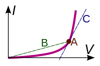
In other cases, such as atransformer,diodeorbattery,VandIare not directly proportional. The ratioV/Iis sometimes still useful, and is referred to as achordal resistanceorstatic resistance,[1][2]since it corresponds to the inverse slope of achordbetween the origin and anI–Vcurve.In other situations, thederivativemay be most useful; this is called thedifferential resistance.
Introduction
[edit]
In thehydraulic analogy,current flowing through a wire (orresistor) is like water flowing through a pipe, and thevoltage dropacross the wire is like thepressure dropthat pushes water through the pipe. Conductance is proportional to how much flow occurs for a given pressure, and resistance is proportional to how much pressure is required to achieve a given flow.
Thevoltage drop(i.e., difference between voltages on one side of the resistor and the other), not thevoltageitself, provides the driving force pushing current through a resistor. In hydraulics, it is similar: the pressure difference between two sides of a pipe, not the pressure itself, determines the flow through it. For example, there may be a large water pressure above the pipe, which tries to push water down through the pipe. But there may be an equally large water pressure below the pipe, which tries to push water back up through the pipe. If these pressures are equal, no water flows. (In the image at right, the water pressure below the pipe is zero.)
The resistance and conductance of a wire, resistor, or other element is mostly determined by two properties:
- geometry (shape), and
- material
Geometry is important because it is more difficult to push water through a long, narrow pipe than a wide, short pipe. In the same way, a long, thin copper wire has higher resistance (lower conductance) than a short, thick copper wire.
Materials are important as well. A pipe filled with hair restricts the flow of water more than a clean pipe of the same shape and size. Similarly,electronscan flow freely and easily through acopperwire, but cannot flow as easily through asteelwire of the same shape and size, and they essentially cannot flow at all through aninsulatorlikerubber,regardless of its shape. The difference between copper, steel, and rubber is related to their microscopic structure andelectron configuration,and is quantified by a property calledresistivity.
In addition to geometry and material, there are various other factors that influence resistance and conductance, such as temperature; seebelow.
Conductors and resistors
[edit]
Substances in which electricity can flow are calledconductors.A piece of conducting material of a particular resistance meant for use in a circuit is called aresistor.Conductors are made of high-conductivitymaterials such as metals, in particular copper and aluminium. Resistors, on the other hand, are made of a wide variety of materials depending on factors such as the desired resistance, amount of energy that it needs to dissipate, precision, and costs.
Ohm's law
[edit]
For many materials, the currentIthrough the material is proportional to the voltageVapplied across it: over a wide range of voltages and currents. Therefore, the resistance and conductance of objects or electronic components made of these materials is constant. This relationship is calledOhm's law,and materials which obey it are calledohmicmaterials. Examples of ohmic components are wires andresistors.Thecurrent–voltage graphof an ohmic device consists of a straight line through the origin with positiveslope.
Other components and materials used in electronics do not obey Ohm's law; the current is not proportional to the voltage, so the resistance varies with the voltage and current through them. These are callednonlinearornon-ohmic.Examples includediodesandfluorescent lamps.
Relation to resistivity and conductivity
[edit]
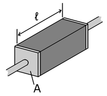
The resistance of a given object depends primarily on two factors: what material it is made of, and its shape. For a given material, the resistance is inversely proportional to the cross-sectional area; for example, a thick copper wire has lower resistance than an otherwise-identical thin copper wire. Also, for a given material, the resistance is proportional to the length; for example, a long copper wire has higher resistance than an otherwise-identical short copper wire. The resistanceRand conductanceGof a conductor of uniform cross section, therefore, can be computed as
whereis the length of the conductor, measured inmetres(m),Ais the cross-sectional area of the conductor measured insquare metres(m2),σ(sigma) is theelectrical conductivitymeasured insiemensper meter (S·m−1), andρ(rho) is theelectrical resistivity(also calledspecific electrical resistance) of the material, measured in ohm-metres (Ω·m). The resistivity and conductivity are proportionality constants, and therefore depend only on the material the wire is made of, not the geometry of the wire. Resistivity and conductivity arereciprocals:.Resistivity is a measure of the material's ability to oppose electric current.
This formula is not exact, as it assumes thecurrent densityis totally uniform in the conductor, which is not always true in practical situations. However, this formula still provides a good approximation for long thin conductors such as wires.
Another situation for which this formula is not exact is withalternating current(AC), because theskin effectinhibits current flow near the center of the conductor. For this reason, thegeometricalcross-section is different from theeffectivecross-section in which current actually flows, so resistance is higher than expected. Similarly, if two conductors near each other carry AC current, their resistances increase due to theproximity effect.Atcommercial power frequency,these effects are significant for large conductors carrying large currents, such asbusbarsin anelectrical substation,[3]or large power cables carrying more than a few hundred amperes.
The resistivity of different materials varies by an enormous amount: For example, the conductivity ofteflonis about 1030times lower than the conductivity of copper. Loosely speaking, this is because metals have large numbers of "delocalized" electrons that are not stuck in any one place, so they are free to move across large distances. In an insulator, such as Teflon, each electron is tightly bound to a single molecule so a great force is required to pull it away.Semiconductorslie between these two extremes. More details can be found in the article:Electrical resistivity and conductivity.For the case ofelectrolytesolutions, see the article:Conductivity (electrolytic).
Resistivity varies with temperature. In semiconductors, resistivity also changes when exposed to light. Seebelow.
Measurement
[edit]
An instrument for measuring resistance is called anohmmeter.Simple ohmmeters cannot measure low resistances accurately because the resistance of their measuring leads causes a voltage drop that interferes with the measurement, so more accurate devices usefour-terminal sensing.
Typical values
[edit]| Component | Resistance (Ω) |
|---|---|
| 1 meter of copper wire with 1 mm diameter | 0.02[a] |
| 1 kmoverhead power line(typical) | 0.03[5] |
| AA battery(typicalinternal resistance) | 0.1[b] |
| Incandescent light bulbfilament (typical) | 200–1000[c] |
| Human body | 1000–100,000[d] |
Static and differential resistance
[edit]Many electrical elements, such asdiodesandbatteriesdonotsatisfyOhm's law.These are callednon-ohmicornon-linear,and theircurrent–voltage curvesarenotstraight lines through the origin.
Resistance and conductance can still be defined for non-ohmic elements. However, unlike ohmic resistance, non-linear resistance is not constant but varies with the voltage or current through the device; i.e., itsoperating point.There are two types of resistance:[1][2]
- Static resistance
This corresponds to the usual definition of resistance; the voltage divided by the current
It is the slope of the line (chord) from the origin through the point on the curve. Static resistance determines the power dissipation in an electrical component. Points on the current–voltage curve located in the 2nd or 4th quadrants, for which the slope of the chordal line is negative, havenegative static resistance.Passivedevices, which have no source of energy, cannot have negative static resistance. However active devices such as transistors orop-ampscan synthesize negative static resistance with feedback, and it is used in some circuits such asgyrators.- Differential resistance
It is the derivative of the voltage with respect to the current; theslopeof the current–voltage curve at a point
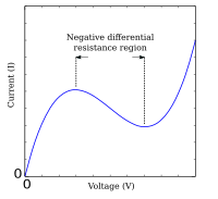
If the current–voltage curve is non-monotonic(with peaks and troughs), the curve has a negative slope in some regions—so in these regions the device hasnegative differential resistance.Devices with negative differential resistance can amplify a signal applied to them, and are used to make amplifiers and oscillators. These includetunnel diodes,Gunn diodes,IMPATT diodes,magnetrontubes, andunijunction transistors.
AC circuits
[edit]Impedance and admittance
[edit]
When an alternating current flows through a circuit, the relation between current and voltage across a circuit element is characterized not only by the ratio of their magnitudes, but also the difference in theirphases.For example, in an idealresistor,the moment when the voltage reaches its maximum, the current also reaches its maximum (current and voltage are oscillating in phase). But for acapacitororinductor,the maximum current flow occurs as the voltage passes through zero and vice versa (current and voltage are oscillating 90° out of phase, see image below).Complex numbersare used to keep track of both the phase and magnitude of current and voltage:
where:
- tis time;
- u(t)andi(t)are the voltage and current as a function of time, respectively;
- U0andI0indicate the amplitude of the voltage and current, respectively;
- is theangular frequencyof the AC current;
- is the displacement angle;
- UandIare the complex-valued voltage and current, respectively;
- ZandYare the compleximpedanceandadmittance,respectively;
- indicates thereal partof acomplex number;and
- is theimaginary unit.
The impedance and admittance may be expressed as complex numbers that can be broken into real and imaginary parts:
whereRis resistance,Gis conductance,Xisreactance,andBissusceptance.These lead to thecomplex numberidentities which are true in all cases, whereasis only true in the special cases of either DC or reactance-free current.
Thecomplex angleis the phase difference between the voltage and current passing through a component with impedanceZ.Forcapacitorsandinductors,this angle is exactly -90° or +90°, respectively, andXandBare nonzero. Ideal resistors have an angle of 0°, sinceXis zero (and henceBalso), andZandYreduce toRandGrespectively. In general, AC systems are designed to keep the phase angle close to 0° as much as possible, since it reduces thereactive power,which does no useful work at a load. In a simple case with an inductive load (causing the phase to increase), a capacitor may be added for compensation at one frequency, since the capacitor's phase shift is negative, bringing the total impedance phase closer to 0° again.
Yis the reciprocal ofZ() for all circuits, just asfor DC circuits containing only resistors, or AC circuits for which either the reactance or susceptance happens to be zero (XorB= 0,respectively) (if one is zero, then for realistic systems both must be zero).
Frequency dependence
[edit]A key feature of AC circuits is that the resistance and conductance can be frequency-dependent, a phenomenon known as theuniversal dielectric response.[8]One reason, mentioned above is theskin effect(and the relatedproximity effect). Another reason is that the resistivity itself may depend on frequency (seeDrude model,deep-level traps,resonant frequency,Kramers–Kronig relations,etc.)
Energy dissipation and Joule heating
[edit]
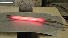
Resistors (and other elements with resistance) oppose the flow of electric current; therefore, electrical energy is required to push current through the resistance. This electrical energy is dissipated, heating the resistor in the process. This is calledJoule heating(afterJames Prescott Joule), also calledohmic heatingorresistive heating.
The dissipation of electrical energy is often undesired, particularly in the case oftransmission lossesinpower lines.High voltage transmissionhelps reduce the losses by reducing the current for a given power.
On the other hand, Joule heating is sometimes useful, for example inelectric stovesand otherelectric heaters(also calledresistive heaters). As another example,incandescent lampsrely on Joule heating: the filament is heated to such a high temperature that it glows "white hot" withthermal radiation(also calledincandescence).
The formula for Joule heating is: wherePis thepower(energy per unit time) converted from electrical energy to thermal energy,Ris the resistance, andIis the current through the resistor.
Dependence on other conditions
[edit]Temperature dependence
[edit]Near room temperature, the resistivity of metals typically increases as temperature is increased, while the resistivity of semiconductors typically decreases as temperature is increased. The resistivity of insulators and electrolytes may increase or decrease depending on the system. For the detailed behavior and explanation, seeElectrical resistivity and conductivity.
As a consequence, the resistance of wires, resistors, and other components often change with temperature. This effect may be undesired, causing an electronic circuit to malfunction at extreme temperatures. In some cases, however, the effect is put to good use. When temperature-dependent resistance of a component is used purposefully, the component is called aresistance thermometerorthermistor.(A resistance thermometer is made of metal, usually platinum, while a thermistor is made of ceramic or polymer.)
Resistance thermometers and thermistors are generally used in two ways. First, they can be used asthermometers:by measuring the resistance, the temperature of the environment can be inferred. Second, they can be used in conjunction withJoule heating(also called self-heating): if a large current is running through the resistor, the resistor's temperature rises and therefore its resistance changes. Therefore, these components can be used in a circuit-protection role similar tofuses,or forfeedbackin circuits, or for many other purposes. In general, self-heating can turn a resistor into anonlinearandhystereticcircuit element. For more details seeThermistor#Self-heating effects.
If the temperatureTdoes not vary too much, alinear approximationis typically used: whereis called thetemperature coefficient of resistance,is a fixed reference temperature (usually room temperature), andis the resistance at temperature.The parameteris an empirical parameter fitted from measurement data. Because the linear approximation is only an approximation,is different for different reference temperatures. For this reason it is usual to specify the temperature thatwas measured at with a suffix, such as,and the relationship only holds in a range of temperatures around the reference.[9]
The temperature coefficientis typically+3×10⁻³K−1to+6×10⁻³K−1for metals near room temperature. It is usually negative for semiconductors and insulators, with highly variable magnitude.[e]
Strain dependence
[edit]Just as the resistance of a conductor depends upon temperature, the resistance of a conductor depends uponstrain.[10]By placing a conductor undertension(a form ofstressthat leads to strain in the form of stretching of the conductor), the length of the section of conductor under tension increases and its cross-sectional area decreases. Both these effects contribute to increasing the resistance of the strained section of conductor. Undercompression(strain in the opposite direction), the resistance of the strained section of conductor decreases. See the discussion onstrain gaugesfor details about devices constructed to take advantage of this effect.
Light illumination dependence
[edit]Some resistors, particularly those made fromsemiconductors,exhibitphotoconductivity,meaning that their resistance changes when light is shining on them. Therefore, they are calledphotoresistors(orlight dependent resistors). These are a common type oflight detector.
Superconductivity
[edit]Superconductorsare materials that have exactly zero resistance and infinite conductance, because they can haveV= 0andI≠ 0.This also means there is nojoule heating,or in other words nodissipationof electrical energy. Therefore, if superconductive wire is made into a closed loop, current flows around the loop forever. Superconductors require cooling to temperatures near4 Kwithliquid heliumfor most metallic superconductors likeniobium–tinalloys, or cooling to temperatures near77 Kwithliquid nitrogenfor the expensive, brittle and delicate ceramichigh temperature superconductors. Nevertheless, there are manytechnological applications of superconductivity,includingsuperconducting magnets.
See also
[edit]- Conductance quantum
- Von Klitzing constant(its reciprocal)
- Electrical measurements
- Contact resistance
- Electrical resistivity and conductivityfor more information about the physical mechanisms for conduction in materials.
- Johnson–Nyquist noise
- Quantum Hall effect,a standard for high-accuracy resistance measurements.
- Resistor
- RKM code
- Series and parallel circuits
- Sheet resistance
- SI electromagnetism units
- Thermal resistance
- Voltage divider
- Voltage drop
Footnotes
[edit]- ^The resistivity of copper is about1.7×10−8Ω⋅m.[4]
- ^For a fresh Energizer E91 AA alkaline battery, the internal resistance varies from0.9 Ωat−40 °C,to0.1 Ωat+40 °C.[6]
- ^A60 Wlight bulb (in the USA, with120 Vmains electricity) draws RMS current60 W/120 V=500 mA,so its resistance is120 V/500 mA=240 Ω.The resistance of a60 Wlight bulb in Europe (230 Vmains) is900 Ω.The resistance of a filament is temperature-dependent; these values are for when the filament is already heated up and the light is already glowing.
- ^100 kΩfor dry skin contact,1 kΩfor wet or broken skin contact. High voltage breaks down the skin, lowering resistance to500 Ω.Other factors and conditions are relevant as well. For more details, see theelectric shockarticle, and NIOSH 98-131.[7]
- ^SeeElectrical resistivity and conductivityfor a table. The temperature coefficient of resistivity is similar but not identical to the temperature coefficient of resistance. The small difference is due tothermal expansionchanging the dimensions of the resistor.
References
[edit]- ^abBrown, Forbes T. (2006).Engineering System Dynamics: A Unified Graph-Centered Approach(2nd ed.). Boca Raton, Florida: CRC Press. p. 43.ISBN978-0-8493-9648-9.
- ^abKaiser, Kenneth L. (2004).Electromagnetic Compatibility Handbook.Boca Raton, Florida: CRC Press. pp. 13–52.ISBN978-0-8493-2087-3.
- ^Fink & Beaty (1923). "Standard Handbook for Electrical Engineers".Nature.111(2788) (11th ed.): 17–19.Bibcode:1923Natur.111..458R.doi:10.1038/111458a0.hdl:2027/mdp.39015065357108.S2CID26358546.
- ^Cutnell, John D.;Johnson, Kenneth W.(1992).Physics(2nd ed.). New York: Wiley. p. 559.ISBN978-0-471-52919-4.
- ^McDonald, John D. (2016).Electric Power Substations Engineering(2nd ed.). Boca Raton, Florida: CRC Press. pp. 363ff.ISBN978-1-4200-0731-2.
- ^Battery internal resistance(PDF)(Report). Energizer Corp. Archived fromthe original(PDF)on 11 January 2012.Retrieved13 December2011.
- ^"Worker Deaths by Electrocution"(PDF).National Institute for Occupational Safety and Health.Publication No. 98-131.Retrieved2 November2014.
- ^Zhai, Chongpu; Gan, Yixiang; Hanaor, Dorian; Proust, Gwénaëlle (2018). "Stress-dependent electrical transport and its universal scaling in granular materials".Extreme Mechanics Letters.22:83–88.arXiv:1712.05938.Bibcode:2018ExML...22...83Z.doi:10.1016/j.eml.2018.05.005.S2CID51912472.
- ^Ward, M.R. (1971).Electrical Engineering Science.McGraw-Hill. pp. 36–40.
- ^Meyer, Sebastian; et al. (2022), "Characterization of the deformation state of magnesium by electrical resistance",Volume 215,Scripta Materialia, vol. 215, p. 114712,doi:10.1016/j.scriptamat.2022.114712,S2CID247959452
External links
[edit]- "Resistance calculator".Vehicular Electronics Laboratory. Clemson University. Archived fromthe originalon 11 July 2010.
- "Electron conductance models using maximal entropy random walks".wolfram.com.Wolfram Demonstrantions Project.


![{\displaystyle {\begin{aligned}R&=\rho {\frac {\ell }{A}},\\[5pt]G&=\sigma {\frac {A}{\ell }}\,.\end{aligned}}}](https://wikimedia.org/api/rest_v1/media/math/render/svg/b24667605c2703efd09de736ebc63d30be931418)


![{\displaystyle R(T)=R_{0}[1+\alpha (T-T_{0})]}](https://wikimedia.org/api/rest_v1/media/math/render/svg/5b6622ab35566bd32d26736effa752dc8ace798d)


