
Rail fastening system

- Screw for fixing plate to sleeper
- Elastomeric pad supporting rail
- Tension washer
- Rail clamp
- Tensioning bolt (nut not shown)
- Baseplate


Arail fastening systemis a means of fixingrailstorailroad ties(North America) or sleepers (British Isles,Australasia,andAfrica). The termsrail anchors,tie plates,chairsandtrack fastenersare used to refer to parts or all of a rail fastening system. The components of a rail fastening system may also be known collectively asother track material,orOTMfor short. Various types of fastening have been used over the years.
History and overview
[edit]The earliest wooden rails were fixed to wooden sleepers by pegs through holes in the rail, or by nails. By the 18th century, cast iron rails had come into use, and also had holes in the rail itself to allow them to be fixed to a support.[1]18th century developments such as theflanged railandfish bellied railalso had holes in the rail itself; when stone block sleepers were used the nails were driven into a wooden block which had been inserted into a recess in the block. The first chair for a rail is thought to have been introduced in 1797 which attached to the rail on the vertical web via bolts.[2]

By the 1820s the first shaped rolled rails had begun to be produced initially of a T shape which required a chair to hold them; the rails were held in position by iron wedges (which sometimes caused the rail to break when forced in) and later by wooden wedges, which became the standard.[3]In the 1830sRobert L. Stevensinvented the flanged 'tee' rail (actually a distorted I beam), which had a flat bottom and required no chair; a similar design was the contemporarybridge rail(of inverted U section with a bottom flange and laid on longitudinal sleepers); these rails were initially nailed directly to the sleeper.[4]
In North American practice the flanged T rail became the standard, later being used with tie-plates. Elsewhere T rails were replaced bybull head railsof a rounded 'I' or 'figure-8' appearance which still required a supporting chair. Eventually the flanged T rail became commonplace on all the world's railways, though differences in the fixing system still exist.
Symbolism and significance
[edit]A golden tie, also known as agolden spikeor the last spike, may be used to symbolize the start or the completion of an endeavor. These are less often silver or another precious material.
Historically, a ceremonial Golden Spike driven by Leland Stanford connected the rails of the FirstTranscontinental Railroadacross the United States. The valuable rail fastening spike represented the merge of the Central Pacific and Union Pacific railroads on May 10, 1869, at Promontory Summit, Utah Territory. The rail spike has entered American popular consciousness in this manner; the driving of the Golden Spike was a key point in the development of the western seaboard in North America and was recognized as a national achievement and demonstration of progress. Since, railroad workers have been celebrated in popular culture, including in song and verse.[5]
Spikes and screws
[edit]Rail spikes
[edit]

Arail spike(also known as acut spikeorcrampon) is a largenailwith an offset head that is used to secure rails and base plates torailroad ties(sleepers) in the track.Robert Livingston Stevensis credited with the invention of the rail spike,[6]the first recorded use of which was in 1832.[7]The railroad spike was an invention which resulted from the state of industrialisation in the United States in the early 19th century: English mainline railways of that period used heavy and expensive cast iron chairs to secure T-shaped rails; instead, Stevens added a supporting base to the T rail which could be fixed with a simple spike.[8][9]In 1982, the spike was still the most common rail fastening in North America. Common sizes are from9⁄16to10⁄16inch (14 to 16 mm) square and5+1⁄2to 6 inches (140 to 150 mm) long.[10]: 582–3

A rail spike is roughly chisel-shaped and with a flat edged point; the spike is driven with the edge perpendicular to the grain, which gives greater resistance to loosening.[11]The main function is to keep the rail in gauge. When attaching tie plates the attachment is made as strong as possible, whereas when attaching a rail to tie or tie plate the spike is not normally required to provide a strong vertical force, allowing the rail some freedom of movement.[10]: 455, 581–2
On smaller scale jobs, spikes are still driven into wooden sleepers by hammering them with aspike maul,though this manual work has been largely replaced by hydraulic tools[12]and machines, commonly called "spikers"(a machine that removes spikes is called a" spike puller ").[13]Splitting of the wood can be limited by pre-boring spike holes or adding steel bands around the wood.[10]: 455
For use in theUnited Statesthree basic standards are described in theASTMA65 standard, for different carbon steel contents.[14]
Adog spikeis functionally equivalent to a cut spike and is also square in horizontal section and of similar dimensions, but has a pointed penetrating end, and the rail (or "plate holding" ) head has two lugs on either side, giving the impression of a dog's head and aiding spike removal.[15]
Chair screws
[edit]

Achair screw(also known ascoach screw[16]) is a large (~6 in or 152 mm length, slightly under 1 in or 25 mm diameter) metal screw used to fix a chair (for bullhead rail), baseplate (for flat bottom rail) or to directly fasten a rail. Chair screws are screwed into a hole bored in the sleeper.[17]The chair screw has a higher cost to manufacture than the rail spike, but has the advantage of greater fixing power—approximately twice that of a rail spike[18]—and can be used in combination withspring washers.[17]
The chair screw was first introduced in 1860 in France (Frenchtire-fond) and became common in continental Europe.[19]
Adog screwis a tradename variant of the screw spike.[20]
Fang bolts
[edit]Fang boltsorrail anchor boltshave also been used for fixing rails or chairs to sleepers. The fang bolt is a bolt inserted through a hole in the sleeper with a fanged nut that bites into the lower surface of the sleeper. For fastening flat-bottomed rails, an upper-lipped washer can be used to grip the edge of the rail. They are more resistant to loosening by vibrations and movement of the rail.[21]They are thought more effective than spikes and screws and so are used in positions such as switch (point) tieplates[22]and on sharp curves.[23]
Spring spikes
[edit]
Spring spikesorelastic rail spikes[25]are used with flat-bottomed rail, baseplates and wooden sleepers. The spring spike holds the rail down and prevents tipping and also secures the baseplate to the sleeper.[26]TheMacbeth spike(trade name) is a two-pronged U-shapedstaple-like spike bent so that it appears M-shaped when viewed from the side.[27][28]Inverted J-shaped single pointed spikes have also been used.[29]
Fixing equipment
[edit]Thespike maul,also known as aspiking hammer,is a type of sledgehammer with a long thin head which was originally used to drive spikes.[30][31]
Manual hole drilling and spike or screw insertion and removal have been replaced by semi-automated or automated machines, which are driven electrically, by pneumatics, by hydraulics, or are powered by a two-stroke engine. Machines that remove spikes are calledspike pullers.[32][33][34]
Rail supports
[edit]Chairs
[edit]
The earliestrail chairs,made of cast iron and introduced around 1800, were used to fix and support cast-iron rails at their ends;[2]they were also used to join adjacent rails.[35]
In the 1830s rolled T-shaped (orsingle-flanged T parallel rail) and I-shaped (ordouble-flanged T parallelorbullhead) rails were introduced; both required cast-iron chairs to support them.[36]Originally, iron keys were used to wedge the rail into the vertical parallel jaws of the chair; these were superseded by entirely wooden keys.[36]The wooden keys were formed fromoak,steam softened and then compressed with hydraulic presses and stored in a drying house. When inserted into the chair, exposure to the wet atmosphere caused the key to expand, firmly holding the rail.[37]The wedge may be on the inside or outside of the rail. In Britain they were usually on the outside.[38]
Chairs have been fixed to the sleeper using wooden spikes (trenails), screws, fang-bolts or spikes.[39]
In most of the world, flat-bottomed rail and baseplates became the standard. However, in Britain, bullhead rail-and-chairs remained in use until the middle of the twentieth century.[26]
Tie plates
[edit]Atie plate,baseplateorsole plateis a steel plate for centering and reinforcing the attachment point on the rail tracks between aflanged T railand arailroad tie.The tie plate increases bearing area and holds the rail to correctgauge.It is fastened to wooden ties by means ofspikesor bolts through holes in the plate.
The part of the plate under the rail base is tapered, setting the inboardcantof the rail, typically "one in forty" (or 1.4 degrees ). The top surface of the plate has one or two shoulders that fit against the edges of the base of the rail. The double-shoulder type is currently used. Older single-shoulder types were adaptable for various rail widths, with the single shoulder positioned on the outside (field side) of the rails. Most plates are slightly wider on the field side, without which the plates tend to cut more into the outsides of the tie, reducing cant angle.
Many railways use largewood screws,also calledlag screws,to fasten the tie plates (or baseplates) to the railroad ties.
Tie plates came into use around the year 1900, before which time flanged T rail was spiked directly to the ties.
Clips
[edit]A variety of different types of heavy-duty clips are used to fasten the rails to the underlying baseplate, one common one being thePandrolfastener (Pandrol clip), named after its maker, which is shaped like a stubby paperclip.[40]Another one is the Vossloh Tension Clamp.[41]Clips are an alternative to spikes.
The newer Pandrol fastclip is applied at right angles to the rail. Because the clip is captive, it has to be installed at the time of manufacture of the concrete sleeper.
Rail anchors
[edit]
Rail anchors, also called anticreepers, are spring steel clips that attach to the underside of the rail baseplate and bear against the sides of the sleepers to prevent longitudinal movement of the rail, either from changes in temperature or through vibration. Anchors may be attached and removed either by hand with hammers, or by an anchor machine.
Gallery of rail fastening types
[edit]- Rail fastening types
-
 Rail spike with baseplate above the tie
 -
 Baseplate on multi-gauge track
 -
 Track joint and chairs (withfishplatespanning ties)
 -
 Pandrol"e-Clip" fastening
 -
 Pandrol "fastclip" fastening
 -
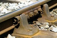
 Tension clamp fastening
 -
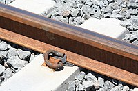
 Bolt clamped fastening
 -
 Steel spring keyed rail in chair


See also
[edit]- Fishplate,the bar that bolts two sections of rail together
- Permanent wayandpermanent way (history),descriptions of the entire track system.
- Rail sabotage
References
[edit]- ^Raidabaugh (1915),p. 5-7.
- ^abOrigin and Development of the Railway Rail, G. P. Raidabaugh, pp.8-9
- ^Origin and Development of the Railway Rail, G. P. Raidabaugh, pp.14-19
- ^Origin and Development of the Railway Rail, G. P. Raidabaugh, pp.19-24
- ^Norm Cohen; David Cohen (2000).Long steel rail: the railroad in American folksong.University of Illinois Press.ISBN9780252068812.
- ^"October 18 - Today in Science History".www.todayinsci.com.Robert Livingston Stevens.
- ^George Iles (1912).Leading American inventors.H. Holt and company, New York. p. 23.
- ^Raidabaugh (1915),p. 20.
- ^"The Rail Spike and The Locomotive".chestofbooks.com.Scientific American.
- ^abcHay, William Walter (1953).Railroad Engineering, Volume 1.John Wiley & Sons.
- ^"railroad spikes".www.sizes.com.
- ^"Spike Drivers | Stanley Hydraulic".www.stanleyhydraulics.com.Retrieved2016-12-23.
- ^Solomon (2001),p. 61-64.
- ^"ASTM A65 - 07".www.astm.org.ASTM International (American Society for Testing and Materials).
- ^Mundrey (2000),p. 130–131.
- ^"Hay J.G., B.Sc, A.M.I.C.E., M.I.Struct.E. - Railway Sleepers and Fastenings on the South African Railways - Civil Engineer in South Africa, June 1962, p105",www.journals.co.za
- ^abRailroad engineering, Volume 1, William Walter Hay, pp.585
- ^Orrock (1918),p. 188-204.
- ^Sellew (1915),p. 161-163.
- ^"AJAX - Dog Screw Railway Fasteners for Rail Tracks With Timber Sleepers",www.railway-technology.com
- ^Railway Appliances, John Wolfe Barry, pp.53-54,73
- ^Mundrey (2000),p. 156–157.
- ^William Hemingway Mills(1898).Railway Construction.Longmans, Green, and Co. pp. 224,alsofig.331–334 (p.221).
- ^Wolfgang Schiemann (2002).Schienenverkehrstechnik: Grundlagen der Gleistrassierung.Teubner B.G. p. 283.ISBN3519003635.
- ^Bonnett (2005),p. 65, 5.10 Rail Fastenings, Baseplates and Pads
- ^abCraig (2015).
- ^National Research Council (U.S.). Railroad Research Information Service; United States. Federal Railroad Administration (1973).Special bibliography: safety-related technology.National Academies. 032978 Spring Steel Rail Spikes(from Railway Gazette, Feb. 1948, Vol.88, pp.191-2).
- ^Ellis (2006),p. 211, Macbeth Spike.
- ^Ellis (2006),p. 114, Elastic Spike.
- ^Sellew (1915),p. 215-216.
- ^Ron Fitch (2006).Australian Railwayman: From Cadet Engineer to Railways Commissioner.Rosenberg Publishing. p. 220.
- ^Solomon (2001),p. 59–62.
- ^"Workin' on the Railroad".Popular Mechanics.84(4). Hearst Magazines: 20–27. October 1945.ISSN0032-4558.
- ^"Mechanised section gang now lays railroad ties".Popular Science.168(2). Bonnier Corporation: 168–9. February 1956.ISSN0161-7370.
- ^Raidabaugh (1915),p. 11-12.
- ^abClark (1855),p. 280.
- ^Williams, Frederick Smeaton (1852).Our Iron Roads: Their History, Construction and Influences: With numerous illustrations.Ingram. pp. 199–200.
- ^Railway Appliances, John Wolfe Barry, pp.43-51
- ^Railway Appliances, John Wolfe Barry, pp.71
- ^"Pandrol - Pandrol - The future of rail fastenings".www.pandrol.com.
- ^"vossloh-fastening-systems.com - Home".www.vosslo-fastening-systems.de.
Bibliography
[edit]- Barry, John Wolfe (1876).Railway Appliances.Longmans, Green and co. (reprint BiblioBazaar, LLC, 2008).ISBN9780559022982.
- Bonnett, Clifford F. (2005).Practical Railway Engineering(2nd ed.). London, UK:Imperial College Press.ISBN978-1-86094-515-1.OCLC443641662.
- Clark, Daniel Kinnear (1855).Railway machinery: a treatise on the mechanical engineering of railways: embracing the principles and construction of rolling and fixed plant; illustrated by a series of plates on a large scale, and by numerous engravings on wood, Volume 2.Blackie and Son.
- Craig, Colin (2015)."Modern Permanent Way".The Manchester Model Railway Society.
- Crandall, Charles Lee; Barnes, Fred Asa (1913).Railroad Construction.McGraw-Hill.
- Ellis, Iain (2006).Ellis' British Railway Engineering Encyclopaedia.Lulu.com.ISBN978-1847286437.
- Hay, William Walter (1953).Railroad Engineering, Volume 1(1st ed.). John Wiley & Sons.
- Hay, William Walter (1982).Railroad engineering, Volume 1(2nd ed.). John Wiley and Sons.ISBN978-0471364009.
- Mundrey, J.S. (2000).Railway Track Engineering.Tata McGraw-Hill. pp. 130–131.ISBN978-0074637241.
- Orrock, John Wilson (1918)."Railroad Structure and Estimates".J. Wiley & Sons, New York.
- Raidabaugh, G.P. (1915).Origin and Development of the Railway Rail: English and American Wood, Iron and Steel.Kohn & Pollock, Baltimore.ISBN9781408637654.
- Sellew, William (1915).Railway Maintenance Engineering - With Notes on Construction.D. Van Nostrand Company.ISBN9781445591773.
- Solomon, Brian (2001).Railway Maintenance: The Men and Machines That Keep the Railroads Running.MBI Publishing Company.ISBN978-0760309759.
Further reading
[edit]- Railway locomotives and cars, Volume 6.Simmons-Boardman Pub. Corp. 1838. From the American Journal of Science and Arts "Experiments on the adhesion of iron spikes of various forms, when driven into different specimins of timber"; by Walter B. Johnson, Professor of mechanics and natural philosophy in the Franklin Institute, Philadelphia, pp.357-360.
External links
[edit]- Images:Keith Norgrove; et al."Scalefour Society - Track Details in Photographs II".www.scalefour.org.Scalefour Society.
- a closeup view of Pandrol fastclip