Orthographic projection
| Part of a series on |
| Graphical projection |
|---|
 |
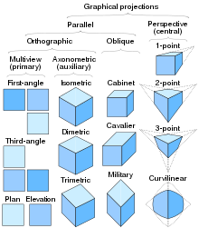
Orthographic projection(alsoorthogonal projectionandanalemma)[a]is a means of representingthree-dimensionalobjects intwo dimensions.Orthographic projection is a form ofparallel projectionin which all the projection lines areorthogonalto theprojection plane,[2]resulting in every plane of the scene appearing inaffine transformationon the viewing surface. The obverse of an orthographic projection is anoblique projection,which is a parallel projection in which the projection lines arenotorthogonal to the projection plane.
The termorthographicsometimes means a technique inmultiview projectionin which principal axes or the planes of the subject are also parallel with the projection plane to create theprimary views.[2]If the principal planes or axes of an object in an orthographic projection arenotparallel with the projection plane, the depiction is calledaxonometricor anauxiliary views.(Axonometric projectionis synonymous withparallel projection.) Sub-types ofprimary viewsincludeplans,elevations,andsections;sub-types ofauxiliary viewsincludeisometric,dimetric,andtrimetric projections.
A lens that provides an orthographic projection is anobject-space telecentric lens.
Geometry[edit]


A simple orthographicprojectiononto theplanez= 0 can be defined by the following matrix:
For each pointv= (vx,vy,vz), the transformed pointPvwould be
Often, it is more useful to usehomogeneous coordinates.The transformation above can be represented for homogeneous coordinates as
For each homogeneous vectorv= (vx,vy,vz,1), the transformed vectorPvwould be
Incomputer graphics,one of the most common matrices used for orthographicprojectioncan be defined by a6-tuple,(left,right,bottom,top,near,far), which defines theclippingplanes. These planes form a box with the minimum corner at (left,bottom,-near) and the maximum corner at (right,top,-far).[3]
The box is translated so that its center is at the origin, then it is scaled to the unit cube which is defined by having a minimum corner at (−1,−1,−1) and a maximum corner at (1,1,1).
The orthographic transform can be given by the following matrix:
which can be given as ascalingSfollowed by atranslationTof the form
The inversion of the projection matrixP−1,which can be used as the unprojection matrix is defined:
Types[edit]

Three sub-types of orthographic projection areisometric projection,dimetric projection,andtrimetric projection,depending on the exact angle at which the view deviates from the orthogonal.[2][4]Typically in axonometric drawing, as in other types of pictorials, one axis of space is shown to be vertical.
Inisometric projection,the most commonly used form of axonometric projection in engineering drawing,[5]the direction of viewing is such that the three axes of space appear equallyforeshortened,and there is a common angle of 120° between them. As the distortion caused by foreshortening is uniform, the proportionality between lengths is preserved, and the axes share a common scale; this eases one's ability to take measurements directly from the drawing. Another advantage is that 120° angles are easily constructed using only acompass and straightedge.
Indimetric projection,the direction of viewing is such that two of the three axes of space appear equally foreshortened, of which the attendant scale and angles of presentation are determined according to the angle of viewing; the scale of the third direction is determined separately.
Intrimetric projection,the direction of viewing is such that all of the three axes of space appear unequally foreshortened. The scale along each of the three axes and the angles among them are determined separately as dictated by the angle of viewing. Trimetric perspective is seldom used in technical drawings.[4]
Multiview projection[edit]

Inmultiview projection,up to six pictures of an object are produced, calledprimary views,with each projection plane parallel to one of the coordinate axes of the object. The views are positioned relative to each other according to either of two schemes:first-angleorthird-angleprojection. In each, the appearances of views may be thought of as beingprojectedonto planes that form a six-sided box around the object. Although six different sides can be drawn, usually three views of a drawing give enough information to make a three-dimensional object. These views are known asfront view(alsoelevation),top view(alsoplan) andend view(alsosection). When the plane or axis of the object depicted isnotparallel to the projection plane, and where multiple sides of an object are visible in the same image, it is called anauxiliary view.Thusisometric projection,dimetric projectionandtrimetric projectionwould be consideredauxiliary viewsin multiview projection. A typical characteristic of multiview projection is that one axis of space is usually displayed as vertical.
Cartography[edit]

An orthographic projection map is amap projectionofcartography.Like thestereographic projectionandgnomonic projection,orthographic projection is aperspective (or azimuthal) projection,in which thesphereis projected onto atangent planeorsecant plane.Thepoint of perspectivefor the orthographic projection is atinfinitedistance. It depicts ahemisphereof theglobeas it appears fromouter space,where thehorizonis agreat circle.The shapes and areas aredistorted,particularly near the edges.[6][7]
The orthographic projection has been known since antiquity, with its cartographic uses being well documented.Hipparchusused the projection in the 2nd century BC to determine the places of star-rise and star-set. In about 14 BC, Roman engineerMarcus Vitruvius Pollioused the projection to construct sundials and to compute sun positions.[7]
Vitruvius also seems to have devised the term orthographic – from the Greekorthos( "straight" ) andgraphē( "drawing" ) – for the projection. However, the nameanalemma,which also meant a sundial showing latitude and longitude, was the common name untilFrançois d'Aguilonof Antwerp promoted its present name in 1613.[7]
The earliest surviving maps on the projection appear as woodcut drawings of terrestrial globes of 1509 (anonymous), 1533 and 1551 (Johannes Schöner), and 1524 and 1551 (Apian).[7]
Notes[edit]
References[edit]
- ^Sawyer, F.,Of Analemmas, Mean Time and the Analemmatic Sundial
- ^abcMaynard, Patric (2005).Drawing Distinctions: The Varieties of Graphic Expression.Cornell University Press. p. 22.ISBN0-8014-7280-6.
- ^Thormählen, Thorsten (November 26, 2021)."Graphics Programming – Cameras: Parallel Projection – Part 6, Chapter 2".Mathematik Uni Marburg.pp. 8 ff.Retrieved2022-04-22.
- ^abMcReynolds, Tom; David Blythe (2005).Advanced graphics programming using openGL.Elsevier. p. 502.ISBN1-55860-659-9.
- ^Godse, Atul P. (1984).Computer graphics.Technical Publications. p. 29.ISBN81-8431-558-9.
- ^Snyder, J. P. (1987).Map Projections—A Working Manual (US Geologic Survey Professional Paper 1395).Washington, D.C.: US Government Printing Office. pp. 145–153.
- ^abcdSnyder, John P. (1993).Flattening the Earth: Two Thousand Years of Map Projectionspp. 16–18. Chicago and London: The University of Chicago Press.ISBN0-226-76746-9.


