
Area rule

TheWhitcomb area rule,named afterNACAengineerRichard Whitcomband also called thetransonic area rule,is a design procedure used to reduce anaircraft'sdragattransonicspeeds which occur between aboutMach0.75 and 1.2. For supersonic speeds a different procedure called thesupersonic area rule,developed by NACA aerodynamicistRobert Jones,is used.
Transonic is one of the most important speed ranges for commercial and militaryfixed-wing aircrafttoday, with transonic acceleration an important performance requirement for combat aircraft and which is improved by reductions in transonic drag.
Description
[edit]At high-subsonic flight speeds, the local speed of the airflow can reach the speed of sound where the flow accelerates around theaircraftbody andwings.The speed at which this development occurs varies from aircraft to aircraft and is known as thecritical Mach number.The resultingshock wavesformed at these zones of sonic flow cause a sudden increase indrag,calledwave drag.To reduce the number and strength of these shock waves, anaerodynamicshape should change incross sectionalarea as smoothly as possible from front to rear.
Transonic area rule
[edit]The area rule says that two airplanes with the same longitudinal cross-sectional area distribution have the same wave drag, independent of how the area is distributed laterally (i.e. in the fuselage or in the wing). Furthermore, to avoid the formation of strong shock waves the external shape of the aircraft has to be carefully arranged so that the cross-sectional area changes as smoothly as possible going from nose to tail. At the location of the wing, the fuselage is narrowed or "waisted". Fuselage cross-sectional area may need to be reduced by flattening the sides of the fuselage below a bubble canopy and at the tail surfaces to compensate for their presence, both of which were done on theHawker Siddeley Buccaneer.[1]
Supersonic area rule
[edit]A different area rule, known as the supersonic area rule, developed by NACA aerodynamicist Robert Jones in "Theory of wing-body drag at supersonic speeds",[2]is applicable at speeds beyond transonic, and in this case, the cross-sectional area requirement is established with relation to the angle of the Mach cone for the design speed. For example, consider that at Mach 1.3 the angle of the Mach cone generated by the nose of the aircraft will be at an angle μ = arcsin(1/M) = 50.3° (where μ is the angle of the Mach cone, also known asMach angle,and M is theMach number). In this case the "perfect shape" is biased rearward; therefore, aircraft designed for lower wave drag at supersonic speed usually have wings towards the rear.[2]
Sears–Haack body
[edit]A superficially related concept is theSears–Haack body,the shape of which allows minimum wave drag for a given length and a given volume. However, the Sears–Haack body shape is derived starting with thePrandtl–Glauert equationwhich approximately governs small-disturbance subsonic flows, as well as Ackeret Theory, which closely describes supersonic flow. Both methods lose validity for transonic flows where the area rule applies, due to assumptions made in their derivations. So although the Sears–Haack body shape, being smooth, will have favorable wave drag properties according to the area rule, it is not theoretically optimum.[3]
History
[edit]Germany
[edit]

The area rule was discovered byOtto Frenzlwhen comparing a swept wing with a w-wing with extreme high wave drag[4]while working on a transonic wind tunnel atJunkersworks in Germany between 1943 and 1945. He wrote a description on 17 December 1943, with the titleAnordnung von Verdrängungskörpern beim Hochgeschwindigkeitsflug( "Arrangement of Displacement Bodies in High-Speed Flight" ); this was used in a patent filed in 1944.[5]The results of this research were presented to a wide circle in March 1944 by Theodor Zobel at theDeutsche Akademie der Luftfahrtforschung(German Academy of Aeronautics Research) in the lecture "Fundamentally new ways to increase performance of high speed aircraft."[6]
Subsequent German wartime aircraft design took account of the discovery, evident in slim mid-fuselage of aircraft including theMesserschmitt P.1112,P.1106andFocke-Wulf 1000x1000x1000type A long-range bomber, but also apparent in delta wing designs including theHenschel Hs 135.Several other researchers came close to developing a similar theory, notablyDietrich Küchemannwho designed a tapered fighter that was dubbed the "Küchemann Coke Bottle" when it was discovered by US forces in 1946. In this case Küchemann arrived at the theory by studying airflow, notably the interference, or local flow streamlines, at the junction between a fuselage andswept wing.The fuselage was contoured, or waisted, to match the flow. The shaping requirement of this "near field" approach would also result from Whitcomb's later "far field" approach to drag reduction using his Sonic area rule.[7]
United States
[edit]Wallace D. Hayes,a pioneer ofsupersonicflight, developed the transonic area rule in publications beginning in 1947 with his Ph.D. thesis at theCalifornia Institute of Technology.[8]

Richard T. Whitcomb,after whom the rule is named, independently discovered this rule in 1952, while working at theNational Advisory Committee for Aeronautics(NACA). While using the new Eight-Foot High-Speed Tunnel, awind tunnelwith performance up to Mach 0.95 at NACA'sLangley Research Center,he was surprised by the increase in drag due to shock wave formation. Whitcomb realized that, for analytical purposes, an airplane could be reduced to a streamlined body of revolution, elongated as much as possible to mitigate abrupt discontinuities and, hence, equally abrupt drag rise.[9]The shocks could be seen usingSchlieren photography,but the reason they were being created at speeds far below the speed of sound, sometimes as low as Mach 0.70, remained a mystery.
In late 1951, the lab hosted a talk byAdolf Busemann,a famous German aerodynamicist who had moved to Langley afterWorld War II.He talked about the behavior of airflow around an airplane as its speed approached the critical Mach number, when air no longer behaved as an incompressible fluid. Whereas engineers were used to thinking of air flowing smoothly around the body of the aircraft, at high speeds it simply did not have time to "get out of the way", and instead started to flow as if it were rigid pipes of flow, a concept Busemann referred to as "streampipes", as opposed tostreamlines,and jokingly suggested that engineers had to consider themselves "pipefitters".
Several days later Whitcomb had a "Eureka"moment. The reason for the high drag was that the" pipes "of air were interfering with each other in three dimensions. One does not simply consider the air flowing over a 2D cross-section of the aircraft as others could in the past; now they also had to consider the air to the" sides "of the aircraft which would also interact with these streampipes. Whitcomb realized that the shaping had to apply to the aircraftas a whole,rather than just to the fuselage. That meant that the extra cross-sectional area of the wings and tail had to be accounted for in the overall shaping, and that the fuselage should actually be narrowed where they meet to more closely match the ideal.
Applications
[edit]The first aircraft where the area rule was consequently implemented was the German bombertestbedJunkers Ju-287(1944).[10]Other corresponding German designs were not completed due to the end of the war or even remained in the planning stage.
When the area rule was re-discovered by Whitcomb, it was made available to the U.S. aircraft industry on a secret basis for military programs from 1952[11]and it was reported in 1957 for civilian programs. [12] Convair and Grumman, with Whitcomb's help, used it concurrently to design theGrumman F-11 Tigerand to redesign theConvair F-102.[13]TheGrumman F-11 Tigerwas the first of the two aircraft to fly and had been designed using the area rule from the outset.[14]The ConvairF-102 Delta Daggerhad to be redesigned as it had been unable to reach Mach 1 although its design speed was Mach 1.2. The expectation that it would reach design speed had been based on optimistic wind-tunnel drag predictions.[15][16]Modifications which included indenting the fuselage beside the wings and adding more volume to the rear of the aircraft, reduced the transonic drag significantly and the Mach 1.2 design speed was reached. The reason for using the area rule on these fighter aircraft was to reduce the peak value of the drag which occurs at Mach 1 and so enable supersonic speeds with less thrust than would otherwise have been necessary.
In 1957 a modified area rule was available for raising the subsonic cruise speed of transport aircraft by 50 mph.[12]The cruise speed is limited by the sudden increase in drag which indicates the presence of local supersonic flow on top of the wing. Whitcomb's modified rule reduced the supersonic speed before the shock, which weakened it and reduced the drag associated with it. TheConvair 990had bumps calledantishock bodiesadded to the top surface of the wing with the intent of achieving the required cruise speed. However, the area distribution in the channels formed by the nacelle/pylon/wing surfaces also caused supersonic velocities and was the source of significant drag. An area-rule technique, so-called channel area-ruling, was applied to achieve the required cruise speed.
Designers atArmstrong-Whitworthtook the sonic area rule a step further in their proposed M-Wing, in which the wing was first swept forward and then to the rear. This allowed the fuselage to be narrowed in front of the root as well as behind it, leading to a smoother fuselage that remained wider on average than one using a classic swept wing.
The extension behind the flight deck on theRockwell B-1 LancerandBoeing 747was added to improve the cross-sectional area distribution according to the area rule.[17]
Aircraft designed according to Whitcomb's area rule (such as theF-102 Delta Daggerand theNorthrop F-5) looked odd when they first appeared and were sometimes dubbed "flyingCoke bottles",but this became an expected part of the appearance of some transonic aircraft. Visually-apparent indications that the area rule has defined the shape of an aircraft are fuselage" waisting "and tip-tank shaping as on theNorthrop F-5,and rear fuselage thinning on business jets with rear engines such as theBombardier Global Express.The rule also requires careful positioning of parts, like the boosters and cargo bay on rockets and the shape and location of the canopy on theF-22 Raptor.
The supersonic area rule was applied, at Mach 2, to the prototypeConcorde.The rear fuselage was extended by 3.73m on the production aircraft and reduced wave drag by 1.8%.[18]
Images
[edit]-
 TheF-106 Delta Dart,a development of theF-102 Delta Dagger,shows the "wasp-waisted" shaping due to area rule considerations
 -
 NASAConvair 990withantishock bodieson the rear of the wings
 -
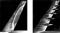 Oilflow visualization of flow separation without and with antishock bodies
 -
 Northrop F-5showing fuselage waisting
 -
 Northrop F-5showing tip-tank shaping
 -
 Bombardier Global Expressshowing rear fuselage thinning between engines
 -
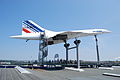
 PrototypeConcordebefore tail was modified using Mach 2 application of area rule
 -
 ProductionConcordewith area ruled tail


See also
[edit]Notes
[edit]- ^From Spitfire To Eurofighter 45 Years of Combat Aircraft Design, Roy Boot,ISBN1 85310 093 5,p.93
- ^abJones, Robert T(1956),Theory of wing-body drag at Supersonic speeds(PDF)(report),UK:NACA, 1284, archived fromthe original(PDF)on 2020-12-05,retrieved2008-09-12.
- ^Spencer, B. Jr; Stivers, L. S. Jr (October 1967)."Studies of optimum body shapes at hypersonic speeds"(PDF).NASA Technical Reports Server.Retrieved4 November2022.
- ^Heinzerling, Werner,Flügelpfeilung und Flächenregel, zwei grundlegende deutsche Patente der Flugzeugaerodynamik[Wing sweep and area rule, two basic German patents of aircraft aerodynamics](PDF)(in German), München,DE:Deutsches Museum, archived fromthe original(PDF)on 2011-07-19,retrieved2010-11-06.
- ^Patentschrift zur Flächenregel[Patent for the area rule](PDF)(in German), 21 Mar 1944.
- ^Meier, Hans-Ulrich (2006),Die Pfeilflügelentwicklung in Deutschland bis 1945[The swept-wing development in Germany until 1945] (in German), pp. 166–99,ISBN3-7637-6130-6.
- ^Design For Combat Aircraft, Ray Whitford 1987,ISBN0 7106 0426 2,Fig.161
- ^Wallace Hayes(obituary), Princeton.
- ^Hallion, Richard P."The NACA, NASA, and the Supersonic-Hypersonic Frontier"(PDF).NASA.NASA Technical Reports Server.Retrieved8 September2011.
- ^Meier, Hans-Ulrich (2006),Die Pfeilflügelentwicklung in Deutschland bis 1945[The swept-wing development in Germany until 1945] (in German), pp. 166–99,ISBN3-7637-6130-6.
- ^"Aviation Week 1955-09-12".12 September 1955.
- ^ab"Aviation Week: August 12, 1957".McGraw-Hill. 12 August 1957. p. 29.Retrieved4 November2022.
- ^"Aviation Week: September 12, 1955".McGraw-Hill. 12 September 1955. p. 12.Retrieved4 November2022.
- ^Design For Air Combat, Ray Whitford,ISBN0 7106 0426 2,p.156
- ^The World's Fighting Planes Fourth and completely revised edition, William Green 1964, MacDonald & Co.(Publishers) Ltd., Gulf House,2 Portman Street, London W.1, p.136
- ^Wallace 1998,p. 144.
- ^Wallace 1998,p. 147.
- ^A Case Study By Aerospatiale And British Aerospace On The Concorde By Jean Rech and Clive S. Leyman, AIAA Professional Study Series, Fig. 3.6
Bibliography
[edit]- Wallace, Lane E (1998). "5". In Mack, Pamela E (ed.).The Whitcomb Area Rule: NACA Aerodynamics Research and Innovation.NASA. pp. 144–47.RetrievedAugust 29,2012.
{{cite book}}:|work=ignored (help)
External links
[edit]- Area rule explained,Aerospace Web.
- Whitcomb Area Rule and Küchemann Carrots,Aerospace Web.
- DGLR documentArchived2016-08-06 at theWayback Machine
- German patent search system– look for Patent DE 932410 filed March 21, 1944.
- 2004: Overuse increases drag but still reduces boom heard on the groundNASA
- See Image 4 for an extreme example: fuselage before wing,PBS.
- The Whitcomb Area Rule: NACA Aerodynamics Research and Innovation,History Nasa.
- Whitcomb, Richard T. (January 1956).A Study of the Zero-Lift Drag-Rise Characteristics of Wing-Body Combinations Near the Speed of Sound(Technical report). National Advisory Committee for Aeronautics.hdl:2060/19930092271– via NASA Technical Reports Server.
- Contemporary reporting and explanation of area rule,Flight global archives