
Cantilever

Acantileveris a rigidstructural elementthat extends horizontally and is unsupported at one end. Typically it extends from a flat vertical surface such as a wall, to which it must be firmly attached. Like other structural elements, a cantilever can be formed as abeam,plate,truss,orslab.
When subjected to astructural loadat its far, unsupported end, the cantilever carries the load to the support where it applies ashear stressand abending moment.[1]
Cantilever construction allows overhanging structures without additional support.
In bridges, towers, and buildings[edit]
Cantilevers are widely found in construction, notably incantilever bridgesandbalconies(seecorbel). In cantilever bridges, the cantilevers are usually built as pairs, with each cantilever used to support one end of a central section. TheForth BridgeinScotlandis an example of a cantilevertruss bridge.A cantilever in a traditionallytimber framedbuilding is called ajettyorforebay.In the southern United States, a historic barn type is the cantilever barn oflog construction.
Temporary cantilevers are often used in construction. The partially constructed structure creates a cantilever, but the completed structure does not act as a cantilever. This is very helpful when temporary supports, orfalsework,cannot be used to support the structure while it is being built (e.g., over a busy roadway or river, or in a deep valley). Therefore, sometruss arch bridges(seeNavajo Bridge) are built from each side as cantilevers until the spans reach each other and are then jacked apart to stress them in compression before finally joining. Nearly allcable-stayed bridgesare built using cantilevers as this is one of their chief advantages. Many box girder bridges are builtsegmentally,or in short pieces. This type of construction lends itself well to balanced cantilever construction where the bridge is built in both directions from a single support.
These structures rely heavily ontorqueand rotational equilibrium for their stability.
In an architectural application,Frank Lloyd Wright'sFallingwaterused cantilevers to project large balconies. The East Stand atElland RoadStadium in Leeds was, when completed, the largest cantilever stand in the world[2]holding 17,000 spectators. Theroofbuilt over the stands atOld Trafforduses a cantilever so that no supports will block views of the field. The old (now demolished)Miami Stadiumhad a similar roof over the spectator area. The largest cantilevered roof in Europe is located atSt James' ParkinNewcastle-Upon-Tyne,the home stadium ofNewcastle United F.C.[3][4]
Less obvious examples of cantilevers are free-standing (vertical)radio towerswithoutguy-wires,andchimneys,which resist being blown over by the wind through cantilever action at their base.
-
 TheForth Bridge,a cantilever truss bridge
 -
 Thisconcrete bridgetemporarily functions as a set of two balanced cantilevers during construction – with further cantilevers jutting out to supportformwork.
 -
 Howrah BridgeinIndia,a cantilever bridge
 -
 A cantilevered balcony of theFallingwaterhouse, byFrank Lloyd Wright
 -
 A cantilevered railroad deck and fence on theCanton Viaduct
 -
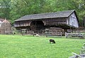 A cantilever barn in ruralTennessee
 -
 Cantilever barn atCades Cove
 -
 A double jettied building in Cambridge, England
 -
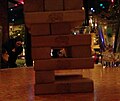 Cantilever occurring in the game "Jenga"
 -

-
 Thisradiographof a "bridge" dental restoration features a cantilevered crown to the left.
 -
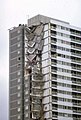 Ronan Point:Structural failure of part of floors cantilevered from a central shaft.


Aircraft[edit]

The cantilever is commonly used in the wings offixed-wing aircraft.Early aircraft had light structures which were braced withwiresandstruts.However, these introduced aerodynamic drag which limited performance. While it is heavier, the cantilever avoids this issue and allows the plane to fly faster.
Hugo Junkerspioneered the cantilever wing in 1915. Only a dozen years after theWright Brothers' initial flights, Junkers endeavored to eliminate virtually all major external bracing members in order to decrease airframe drag in flight. The result of this endeavor was theJunkers J 1pioneering all-metal monoplane of late 1915, designed from the start with all-metal cantilever wing panels. About a year after the initial success of the Junkers J 1,Reinhold PlatzofFokkeralso achieved success with a cantilever-wingedsesquiplanebuilt instead with wooden materials, theFokker V.1.

In the cantilever wing, one or more strong beams, calledspars,run along the span of the wing. The end fixed rigidly to the central fuselage is known as the root and the far end as the tip. In flight, the wings generateliftand the spars carry this load through to the fuselage.
To resist horizontal shear stress from either drag or engine thrust, the wing must also form a stiff cantilever in the horizontal plane. A single-spar design will usually be fitted with a second smaller drag-spar nearer thetrailing edge,braced to the main spar via additional internal members or a stressed skin. The wing must also resist twisting forces, achieved by cross-bracing or otherwise stiffening the main structure.
Cantilever wings require much stronger and heavier spars than would otherwise be needed in a wire-braced design. However, as the speed of the aircraft increases, the drag of the bracing increases sharply, while the wing structure must be strengthened, typically by increasing the strength of the spars and the thickness of the skinning. At speeds of around 200 miles per hour (320 km/h) the drag of the bracing becomes excessive and the wing strong enough to be made a cantilever without excess weight penalty. Increases in engine power through the late 1920s and early 1930s raised speeds through this zone and by the late 1930s cantilever wings had almost wholly superseded braced ones.[5]Other changes such as enclosed cockpits, retractable undercarriage, landing flaps and stressed-skin construction furthered the design revolution, with the pivotal moment widely acknowledged to be theMacRobertson England-Australia air raceof 1934, which was won by ade Havilland DH.88 Comet.[6]
Currently, cantilever wings are almost universal with bracing only being used for some slower aircraft where a lighter weight is prioritized over speed, such as in theultralightclass.
Cantilever in microelectromechanical systems[edit]

Cantilevered beams are the most ubiquitous structures in the field ofmicroelectromechanical systems(MEMS). An early example of a MEMS cantilever is the Resonistor,[7][8]an electromechanical monolithic resonator. MEMS cantilevers are commonly fabricated fromsilicon(Si),silicon nitride(Si3N4), orpolymers. The fabrication process typically involves undercutting the cantilever structure toreleaseit, often with an anisotropic wet ordryetching technique. Without cantilever transducers,atomic force microscopywould not be possible. A large number of research groups are attempting to develop cantilever arrays asbiosensorsfor medical diagnostic applications. MEMS cantilevers are also finding application asradio frequencyfiltersandresonators. The MEMS cantilevers are commonly made asunimorphsorbimorphs.
Two equations are key to understanding the behavior of MEMS cantilevers. The first isStoney's formula,which relates cantilever enddeflectionδ to applied stress σ:

whereisPoisson's ratio,isYoung's modulus,is the beam length andis the cantilever thickness. Very sensitive optical and capacitive methods have been developed to measure changes in the static deflection of cantilever beams used in dc-coupled sensors.


The second is the formula relating the cantileverspring constantto the cantilever dimensions and material constants:


whereis force andis the cantilever width. The spring constant is related to the cantilever resonance frequencyby the usualharmonic oscillatorformula.A change in the force applied to a cantilever can shift the resonance frequency. The frequency shift can be measured with exquisite accuracy usingheterodynetechniques and is the basis of ac-coupled cantilever sensors.


The principal advantage of MEMS cantilevers is their cheapness and ease of fabrication in large arrays. The challenge for their practical application lies in the square and cubic dependences of cantilever performance specifications on dimensions. These superlinear dependences mean that cantilevers are quite sensitive to variation in process parameters, particularly the thickness as this is generally difficult to accurately measure.[9]However, it has been shown that microcantilever thicknesses can be precisely measured and that this variation can be quantified.[10]Controllingresidual stresscan also be difficult.

Chemical sensor applications[edit]
Achemical sensorcan be obtained by coating a recognition receptor layer over the upper side of a microcantilever beam.[12]A typical application is the immunosensor based on anantibodylayer that interacts selectively with a particularimmunogenand reports about its content in a specimen. In the static mode of operation, the sensor response is represented by the beam bending with respect to a reference microcantilever. Alternatively, microcantilever sensors can be operated in the dynamic mode. In this case, the beam vibrates at its resonance frequency and a variation in this parameter indicates the concentration of theanalyte.Recently, microcantilevers have been fabricated that are porous, allowing for a much larger surface area foranalyteto bind to, increasing sensitivity by raising the ratio of the analyte mass to the device mass.[13]Surface stress on microcantilever, due to receptor-target binding, which produces cantilever deflection can be analyzed using optical methods like laser interferometry. Zhao et al., also showed that by changing the attachment protocol of the receptor on the microcantilever surface, the sensitivity can be further improved when the surface stress generated on the microcantilever is taken as the sensor signal.[14]
See also[edit]
References[edit]
- ^Hool, George A.; Johnson, Nathan Clarke (1920)."Elements of Structural Theory - Definitions".Handbook of Building Construction(Google Books).Vol. 1 (1st ed.). New York:McGraw-Hill.p. 2.Retrieved2008-10-01.
A cantilever beam is a beam having one end rigidly fixed and the other end free.
- ^"GMI Construction wins £5.5M Design and Build Contract for Leeds United Football Club's Elland Road East Stand".Construction News.6 February 1992.Retrieved24 September2012.
- ^IStructE The Structural Engineer Volume 77/No 21, 2 November 1999. James's Park a redevelopment challenge
- ^highbeam;The Architects' Journal.Existing stadiums: St James' Park, Newcastle. 1 July 2005
- ^Stevens, James Hay;The Shape of the Aeroplane,Hutchinson, 1953. pp.78 ff.
- ^Davy, M.J.B.;Aeronautics – Heavier-Than-Air Aircraft,Part I, Historical Survey, Revised edition, Science Museum/HMSO, December 1949. p.57.
- ^ELECTROMECHANICAL MONOLITHIC RESONATOR, US Pat.3417249 - Filed April 29, 1966
- ^R.J. Wilfinger, P. H. Bardell and D. S. Chhabra: The resonistor a frequency selective device utilizing the mechanical resonance of a silicon substrate, IBM J. 12, 113–118 (1968)
- ^P. M. Kosaka, J. Tamayo, J. J. Ruiz, S. Puertas, E. Polo, V. Grazu, J. M. de la Fuente and M. Calleja: Tackling reproducibility in microcantilever biosensors: a statistical approach for sensitive and specific end-point detection of immunoreactions, Analyst 138, 863–872 (2013)
- ^A. R. Salmon, M. J. Capener, J. J. Baumberg and S. R. Elliott: Rapid microcantilever-thickness determination by optical interferometry, Measurement Science and Technology 25, 015202 (2014)
- ^Patrick C. Fletcher; Y. Xu; P. Gopinath; J. Williams; B. W. Alphenaar; R. D. Bradshaw; Robert S. Keynton (2008).Piezoresistive Geometry for Maximizing Microcantilever Array Sensitivity.IEEE Sensors.
- ^Bănică, Florinel-Gabriel (2012).Chemical Sensors and Biosensors:Fundamentals and Applications.Chichester, UK: John Wiley & Sons. p. 576.ISBN978-1-118-35423-0.
- ^Noyce, Steven G.; Vanfleet, Richard R.; Craighead, Harold G.; Davis, Robert C. (1999-02-22)."High surface-area carbon microcantilevers".Nanoscale Advances.1(3): 1148–1154.doi:10.1039/C8NA00101D.PMC9418787.PMID36133213.
- ^Zhao, Yue; Gosai, Agnivo; Shrotriya, Pranav (1 December 2019)."Effect of Receptor Attachment on Sensitivity of Label Free Microcantilever Based Biosensor Using Malachite Green Aptamer".Sensors and Actuators B: Chemical.300.doi:10.1016/j.snb.2019.126963.
Sources[edit]
- Inglis, Simon:Football Grounds of Britain.CollinsWillow, 1996. page 206.
- Madou, Marc J (2002).Fundamentals of Microfabrication.Taylor & Francis.ISBN0-8493-0826-7.
- Roth, Leland M (1993).Understanding Architecture: Its Elements History and Meaning.Oxford, UK: Westview Press. pp.23–4.ISBN0-06-430158-3.
- Sarid, Dror (1994).Scanning Force Microscopy.Oxford University Press.ISBN0-19-509204-X.
External links[edit]
 Media related toCantilever beamsat Wikimedia Commons
| Authority control databases:National |
|---|