
Incremental encoder

Anincremental encoderis a linear or rotary electromechanical device that has two outputsignals,AandB,which issue pulses when the device is moved.[1]Together, theAandBsignals indicate both the occurrence of and direction of movement. Many incremental encoders have an additional output signal, typically designatedindex[2]orZ,[3]which indicates the encoder is located at a particular reference position. Also, some encoders provide a status output (typically designatedalarm)[4]that indicates internal fault conditions such as abearingfailure or sensor malfunction.
Unlike anabsolute encoder,an incremental encoder does not indicate absolute position;[note 1]it only reports changes in position[3]and, for each reported position change, the direction of movement. Consequently, to determine absolute position at any particular moment, it is necessary to send the encoder signals to anincremental encoder interface,which in turn will "track" and report the encoder's absolute position.
Incremental encoders report position increments nearly instantaneously, which allows them to monitor the movements of high speed mechanisms innear real-time.Because of this, incremental encoders are commonly used in applications that require precise measurement and control of position andvelocity.
Quadrature outputs
[edit]

An incremental encoder employs aquadrature encoderto generate itsAandBoutput signals. The pulses emitted from theAandBoutputs are quadrature-encoded, meaning that when the incremental encoder is moving at a constant velocity, theAandBwaveforms aresquare wavesand there is a 90 degreephase differencebetweenAandB.[2]
At any particular time, the phase difference between theAandBsignals will be positive or negative depending on the encoder's direction of movement. In the case of a rotary encoder, the phase difference is +90° for clockwise rotation and −90° for counter-clockwise rotation, or vice versa, depending on the device design.

The frequency of the pulses on theAorBoutput is directly proportional to the encoder's velocity (rate of position change); higher frequencies indicate rapid movement, whereas lower frequencies indicate slower speeds.[1]Static, unchanging signals are output onAandBwhen the encoder is motionless. In the case of arotary encoder,the frequency indicates the speed of the encoder's shaft rotation, and inlinear encodersthe frequency indicates the speed of linear traversal.
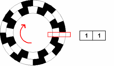
- Conceptual drawings of quadrature encoder sensing mechanisms
Quadrature encoder outputs can be produced by a quadrature-offset pattern read by aligned sensors (left diagram), or by a simple pattern read by offset sensors (right diagram).
-
 Rotary encoder, with correspondingA/Bsignal states shown on the right as the shaft reverses.
 -
 Linear encoder;A&Bsensors are offset by 90° phase of the simple pattern, theRindex signal indicates the encoder is located at its reference position.


Resolution
[edit]The resolution of an incremental encoder is a measure of the precision of the position information it produces. Encoder resolution is typically specified in terms of the number ofA(orB) pulses per unit displacement or, equivalently, the number ofA(orB) square wave cycles per unit displacement. In the case of rotary encoders, resolution is specified as the number of pulses per revolution (PPR) or cycles per revolution (CPR),[3]whereas linear encoder resolution is typically specified as the number of pulses issued for a particular linear traversal distance (e.g., 1000 pulses permm).
This is in contrast to the measurement resolution of the encoder, which is the smallest position change that the encoder can detect. Everysignal edgeonAorBindicates a detected position change. Since each square-wave cycle onA(orB) encompasses four signal edges (risingA,risingB,fallingAand fallingB), the encoder's measurement resolution equals one-fourth of the displacement represented by a fullAorBoutput cycle. For example, a 1000 pulse-per-mm linear encoder has a per-cycle measurement resolution of 1 mm / 1000 cycles = 1 μm, so this encoder's resolution is 1 μm / 4 = 250 nm.
Symmetry and phase
[edit]
When moving at constant velocity, an ideal incremental encoder would output perfect square waves onAandB(i.e., the pulses would be exactly 180° wide and theduty cyclewould be 50%) with a phase difference of exactly 90° betweenAandBsignals. In real encoders, however, due to sensor imperfections and speed variations, the pulse widths are never exactly 180° and the phase difference is never exactly 90°. Furthermore, theAandBpulse widths vary from one cycle to another (and from each other) and the phase difference varies at everyAandBsignal edge. Consequently, both the pulse width and phase difference will vary over a range of values.
For any particular encoder, the pulse width and phase difference ranges are defined by "symmetry" and "phase" (or "phasing" ) specifications, respectively. For example, in the case of an encoder with symmetry specified as 180° ±25°, the width of every output pulse is guaranteed to be at least 155° and no more than 205°. Similarly, with phase specified as 90° ±20°, the phase difference at everyAorBedge will be at least 70° and no more than 110°.
Signal types
[edit]Incremental encoders employ various types of electronic circuits to drive (transmit) their output signals, and manufacturers often have the ability to build a particular encoder model with any of several driver types. Commonly available driver types include open collector, mechanical, push-pull and differential RS-422.
Open collector
[edit]
Open collectordrivers (using anNPN transistoror open drain drivers using ann-type MOSFET) allow operation over a wide range of signal voltages and often can sink significant output current, making them useful for directly drivingcurrent loops,opto-isolatorsandfiber optic transmitters.
Because it cannot source current, the output of an open-collector driver must be connected to a positive DC voltage through apull-up resistor.Some encoders provide an internal resistor for this purpose; others do not and thus require an external pull-up resistor. In the latter case, the resistor typically is located near the encoder interface to improve noise immunity.
The encoder's high-level logic signal voltage is determined by the voltage applied to the pull-up resistor (VOHin the schematic), whereas the low-level output current is determined by both the signal voltage and load resistance (including pull-up resistor). When the driver switches from the low to the high logic level, the load resistance and circuit capacitance act together to form alow-pass filter,which stretches (increases) the signal'srise timeand thus limits its maximum switching frequency.
Mechanical
[edit]
Mechanical (orcontact)[5]incremental encoders use slidingelectrical contactsto directly generate theAandBoutput signals.[2]Typically, the contacts are electrically connected to signal ground when closed so that the outputs will be "driven" low, effectively making them mechanical equivalents of open collector drivers and therefore subject to the same signal conditioning requirements (i.e. external pull-up resistor).
The maximum output frequency is limited by the same factors that affect open-collector outputs, and further limited bycontact bounce(which must be filtered) and by the operating speed of the mechanical contacts, thus making these devices impractical for high frequency operation. Furthermore, the contacts experience mechanical wear under normal operation, which limits thelifeof these devices. On the other hand, mechanical encoders may be relatively inexpensive and have no internal, active electronics. These attributes make mechanical encoders a good fit for hand-operated controls (e.g. volume controls inaudio equipmentand voltage controls in benchpower supplies) and a variety of other low duty, low frequency applications.
Push-pull
[edit]Push-pull outputs(e.g.,TTL) typically are used for direct interface to logic circuitry. These are well-suited to applications in which the encoder and interface are located near each other (e.g., interconnected via printed circuit conductors or short, shielded cable runs) and powered from a common power supply, thus avoiding exposure to electric fields, ground loops and transmission line effects that might corrupt the signals and thereby disrupt position tracking, or worse, damage the encoder interface.
Differential pair
[edit]
DifferentialRS-422signaling is typically preferred when the encoder will output high frequencies or be located far away from the encoder interface,[5][6]or when the encoder signals may be subjected to electric fields or common-mode voltages,[5]or when the interface must be able to detect connectivity problems between encoder and interface. Examples of this includeCMMsandCNCmachinery,industrial robotics,factory automation, andmotion platformsused in aircraft and spacecraft simulators.
When RS-422 outputs are employed, the encoder provides a differential conductor pair for every logic output; for example, "A" and "/A" are commonly-used designations for the active-high and active-low differential pair comprising the encoder'sAlogic output. Consequently, the encoder interface must provide RS-422 line receivers to convert the incoming RS-422 pairs to single-ended logic.[5]
Principal applications
[edit]Position tracking
[edit]Incremental encoders are commonly used to monitor the physical positions of mechanical devices. The incremental encoder is mechanically attached to the device to be monitored so that its output signals will change as the device moves. Example devices include the balls in mechanical computer mice and trackballs, control knobs in electronic equipment, and rotating shafts in radar antennas.
-
 Trackballs and electromechanical computer mice employ two rotary incremental encoders to facilitate position tracking on two axes
 -
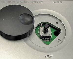 Electronic equipment controls are often implemented with a knob attached to a mechanical encoder (shown with detached knob)
 -
 In commercialmarine radarantennas, a rotary incremental encoder is typically attached to the rotating antenna shaft to monitor the antenna angle
 -
 The location of apipeline video inspectiontractor is typically monitored by a rotary incremental encoder attached to the tractor's cable reel


An incremental encoder does not keep track of, nor do its outputs indicate the current encoder position; it only reports incremental changes in position.[3]Consequently, to determine the encoder's position at any particular moment, it is necessary to provide external electronics which will "track" the position. This external circuitry, which is known as an incremental encoder interface, tracks position by counting incremental position changes.
As it receives each report of incremental position change (indicated by a transition of theAorBsignal), an encoder interface will take into account the phase relationship betweenAandBand, depending on the sign of the phase difference, count up or down. The cumulative "counts" value indicates the distance traveled since tracking began. This mechanism ensures accurate position tracking in bidirectional applications and, in unidirectional applications, prevents false counts that would otherwise result from vibration or mechanical dithering near an AB code transition.
Displacement units
[edit]Often the encoder counts must be expressed in units such as meters, miles or revolutions. In such cases, the counts are converted to the desired units by multiplying by the ratio of encoder displacementper count:


- .

Typically this calculation is performed by a computer which reads the counts from the incremental encoder interface. For example, in the case of a linear incremental encoder that produces 8000 counts per millimeter of travel, the position in millimeters is calculated as follows:
- .

Homing
[edit]In order for an incremental encoder interface to track and report absolute position, the encoder counts must be correlated to a reference position in the mechanical system to which the encoder is attached. This is commonly done byhomingthe system, which consists of moving the mechanical system (and encoder) until it aligns with a reference position, and then jamming[note 2]the associated absolute position counts into the encoder interface's counter.
Aproximity sensoris built into some mechanical systems to facilitate homing, which outputs a signal when the mechanical system is in its "home" (reference) position. In such cases, the mechanical system is homed by moving it until the encoder interface receives the sensor signal, whereupon the corresponding position value is jammed into the position counter.
In some rotating mechanical systems (e.g. rotating radar antennas), the "position" of interest is the rotational angle relative to a reference orientation. These typically employ a rotary incremental encoder that has anindex(orZ) output signal. Theindexsignal is asserted when the shaft is in its reference orientation, which causes the encoder interface to jam the reference angle into its position counter.
Some incremental encoder applications lack reference position detectors and therefore must implement homing by other means. For example a computer, when using a mouse or trackball pointing device, typically will home the device by assuming a central, initial screen position uponbooting,and jam the corresponding counts into the X and Y position counters. In the case of panel encoders used as hand-operated controls (e.g., audio volume control), the initial position typically is retrieved from flash or other non-volatile memory upon power-up and jammed into the position counter, and upon power-down the current position count is saved to non-volatile memory to serve as the initial position for the next power-up.
Speed measurement
[edit]
Incremental encoders are commonly used to measure the speed of mechanical systems. This may be done for monitoring purposes or to provide feedback formotion control,or both.[5]Widespread applications of this include speed control ofradarantenna rotation andmaterial conveyors,and motion control inrobotics,CMMandCNCmachines.
Incremental encoder interfaces are primarily concerned with tracking mechanical displacement and usually do not directly measure speed. Consequently, speed must be indirectly measured by taking thederivativeof the position with respect to time. The position signal is inherentlyquantized,which poses challenges for taking the derivative due to quantization error, especially at low speeds.
Encoder speed can be determined either by counting or by timing the encoder output pulses (or edges).[7]The resulting value indicates a frequency or period, respectively, from which speed can be calculated. The speed is proportional to frequency, and inversely proportional to period.
By frequency
[edit]If the position signal issampled(a discrete time signal), the pulses (or pulse edges) are detected and counted by the interface, and speed is typically calculated by a computer which has read access to the interface. To do this, the computer reads the position countsfrom the interface at timeand then, at some later timereads the counts again to obtain.The average speed during the intervaltois then calculated:[2]


- .

The resulting speed value is expressed as counts per unit time (e.g., counts per second). In practice, however, it is often necessary to express the speed in standardized units such as meters per second, revolutions per minute (RPM), or miles per hour (MPH). In such cases, the software will take into account the relationship between counts and desired distance units, as well as the ratio of the sampling period to desired time units. For example, in the case of a rotary incremental encoder that produces 4096 counts per revolution, which is being read once per second, the software would compute RPM as follows:
- .

When measuring speed this way, the measurement resolution is proportional to both the encoder resolution and the sampling period (the elapsed time between the two samples); measurement resolution will become higher as the sampling period increases.[2]
By period
[edit]Alternatively, a speed measurement can be reported at each encoder output pulse by measuring the pulse width or period. When this method is used, measurements are triggered at specific positions instead of at specific times. The speed calculation is the same as shown above (counts / time), although in this case the measurement start and stop times (and) are provided by a time reference.
This technique avoids position quantization error but introduces errors related to quantization of the time reference. Also, it is more sensitive to sensor non-idealities such as phase errors, symmetry errors, and variations in the transition locations from their nominal values.[8]
Incremental encoder interface
[edit]

Anincremental encoder interfaceis an electronic circuit that receives signals from an incremental encoder, processes the signals to produce absolute position and other information, and makes the resulting information available to external circuitry.
Incremental encoder interfaces are implemented in a variety of ways, including asASICs,asIP blockswithinFPGAs,as dedicated peripheral interfaces inmicrocontrollers,or as software (viainterruptsorpollingGPIOs).
Regardless of the implementation, the interface must sample the encoder'sAandBoutput signals frequently enough to detect every AB state change before the next state change occurs. Upon detecting a state change, it will increment or decrement the position counts based on whetherAleads or trailsB.This is typically done by storing a copy of the previous AB state and, upon state change, using the current and previous AB states to determine movement direction.
Line receivers
[edit]Incremental encoder interfaces use various types of electronic circuits to receive encoder-generated signals. These line receivers serve as buffers to protect downstream interface circuitry and, in many cases, also provide signal conditioning functions.
Single-ended
[edit]Incremental encoder interfaces typically employSchmitt triggerinputs to receive signals from encoders that havesingle-ended(e.g., push-pull, open collector) outputs. This type of line receiver inherently rejects low-level noise (by means of its input hysteresis) and protects downstream circuitry from invalid (and possibly destructive) logic signal levels.
Differential
[edit]RS-422 line receivers are commonly used to receive signals from encoders that have differential outputs. This type of receiver rejects common-mode noise and converts the incoming differential signals to the single-ended form required by downstream logic circuits.
In mission-critical systems, an encoder interface may be required to detect loss of input signals due to encoder power loss, signal driver failure, cable fault or cable disconnect. This is usually accomplished by using enhanced RS-422 line receivers which detect the absence of valid input signals and report this condition via a "signal lost" status output. In normal operation,glitches(brief pulses) may appear on the status outputs during input state transitions; typically, the encoder interface will filter the status signals to prevent these glitches from being erroneously interpreted as lost signals. Depending on the interface, subsequent processing may include generating an interrupt request upon detecting signal loss, and sending notification to the application for error logging or failure analysis.
Clock synchronization
[edit]

An incremental encoder interface largely consists ofsequential logicwhich is paced by aclock signal.However, the incoming encoder signals are asynchronous with respect to the interface clock because their timing is determined solely by encoder movement. Consequently, the output signals from theAandB(alsoZandalarm,if used) line receivers must be synchronized to the interface clock, both to avoid errors due tometastabilityand to coerce the signals into the clock domain of the quadrature decoder.[9]
Typically this synchronization is performed by independent, single-signal synchronizers such as the twoflip-flopsynchronizer seen here. At very high clock frequencies, or when a very low error rate is needed, the synchronizers may include additional flip-flops in order to achieve an acceptably lowbit error rate.[10]
Input filter
[edit]In many cases an encoder interface must filter the synchronized encoder signals before further processing them. This may be required in order to reject low-level noise and brief, large-amplitude noise spikes commonly found in motor applications[11]and, in the case of mechanical-type encoders, to debounceAandBto avoid count errors due to mechanicalcontact bounce.
Hardware-based interfaces often provide programmable filters for the encoder signals, which provide a wide range of filter settings and thus allow them to debounce contacts or suppress transients resulting from noise or slowly slewing signals, as needed. In software-based interfaces,AandBtypically are connected toGPIOsthat are sampled (via polling or edge interrupts) and debounced by software.
Quadrature decoder
[edit]

Incremental encoder interfaces commonly use aquadrature decoderto convert theAandBsignals into thedirectionandcount enable(clock enable) signals needed for controlling a bidirectional (up- and down-counting)synchronous counter.
Typically, a quadrature decoder is implemented as afinite-state machine(FSM) which simultaneously samples theAandBsignals and thus produces amalgamate "AB" samples. As each new AB sample is acquired, the FSM will store the previous AB sample for later analysis. The FSM evaluates the differences between the new and previous AB states and generatesdirectionandcount enablesignals as appropriate for the detected AB state sequence.[11]
| Description | AB state | Outputs | |||||
|---|---|---|---|---|---|---|---|
| Previous | Current | CE | DIR | ERR | |||
| x1 | x2 | x4 | |||||
| Moved one increment in "forward" direction (AleadsB) |
00 | 10 | 1 | 1 | 1 | 1 | 0 |
| 10 | 11 | 0 | 0 | ||||
| 11 | 01 | 1 | |||||
| 01 | 00 | 0 | |||||
| Moved one increment in "reverse" direction (BleadsA) |
00 | 01 | 0 | 0 | |||
| 01 | 11 | 1 | |||||
| 11 | 10 | 0 | |||||
| 10 | 00 | 1 | 1 | ||||
| No detected movement | 00 | 00 | 0 | X | |||
| 01 | 01 | ||||||
| 10 | 10 | ||||||
| 11 | 11 | ||||||
| Moved an indeterminate number of increments | 00 | 11 | 1 | ||||
| 01 | 10 | ||||||
| 10 | 01 | ||||||
| 11 | 00 | ||||||
State transitions
[edit]In any two consecutive AB samples, the logic level ofAorBmay change or both levels may remain unchanged, but in normal operationAandBwill never both change. In this regard, each AB sample is effectively a two-bitGray code.
-
 Movement in forward direction
 -
 Movement in reverse direction
 -
 No movement
 -
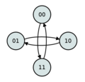 Error
Error


Normal transitions
[edit]When onlyAorBchanges state, it is assumed that the encoder has moved one increment of its measurement resolution and, accordingly, the quadrature decoder will assert itscount enableoutput to allow the counts to change. Depending on the encoder's direction of travel (forward or reverse), the decoder will assert or negate itsdirectionoutput to cause the counts to increment or decrement (or vice versa).
When neitherAnorBchanges, it is assumed that the encoder has not moved and so the quadrature decoder negates itscount enableoutput, thereby causing the counts to remain unchanged.
Errors
[edit]If both theAandBlogic states change in consecutive AB samples, the quadrature decoder has no way of determining how many increments, or in what direction the encoder has moved. This can happen if the encoder speed is too fast for the decoder to process (i.e., the rate of AB state changes exceeds the quadrature decoder's sampling rate; seeNyquist rate) or if theAorBsignal isnoisy.
In many encoder applications this is a catastrophic event because the counter no longer provides an accurate indication of encoder position. Consequently, quadrature decoders often will output an additionalerrorsignal which is asserted when theAandBstates change simultaneously. Due to the severity and time-sensitive nature of this condition, theerrorsignal is often connected to aninterrupt request.
Clock multiplier
[edit]A quadrature decoder does not necessarily allow the counts to change for every incremental position change. When a decoder detects an incremental position change (due to a transition ofAorB,but not both), it may allow the counts to change or it may inhibit counting, depending on the AB state transition and the decoder'sclock multiplier.
The clock multiplier of a quadrature decoder is so named because it results in a count rate which is a multiple of theAorBpulse frequency. Depending on the decoder's design, the clock multiplier may be hardwired into the design or it may be run-time configurable via input signals.
The clock multiplier value may be one, two or four (typically designated "x1", "x2" and "x4", or "1x", "2x" and "4x" ).[12]In the case of a x4 multiplier, the counts will change for every AB state change, thereby resulting in a count rate equal to four times theAorBfrequency. The x2 and x1 multipliers allow the counts to change on some, but not all AB state changes, as shown in the quadrature decoder state table above (note: this table shows one of several possible implementations for x2 and x1 multipliers; other implementations may enable counting at different AB transitions).
Position reporting
[edit]From an application's perspective, the fundamental purpose of an incremental encoder interface is to report position information on demand. Depending on the application, this may be as simple as allowing the computer to read the position counter at any time under program control. In more complex systems, the position counter may be sampled and processed by intermediate state machines, which in turn make the samples available to the computer.
Sample register
[edit]An encoder interface typically employs a sample register to facilitate position reporting. In the simple case where the computer demands position information under program control, the interface will sample the position counter (i.e., copy the current position counts to the sample register) and then the computer will read the counts from the sample register. This mechanism results inatomic operationand thus ensures the integrity of the sample data, which might otherwise be at risk (e.g., if the sample's word size exceeds the computer's word size).[1]
Triggered sampling
[edit]In some cases the computer may not be able to programmatically (viaprogrammed I/O) acquire position information with adequate timing precision. For example, the computer may be unable to demand samples on a timely periodic schedule (e.g., for speed measurement) due to software timing variability. Also, in some applications it is necessary to demand samples upon the occurrence of external events, and the computer may be unable to do so in a timely manner. At higher encoder speeds and resolutions, position measurement errors can occur even when interrupts are used to demand samples, because the encoder may move between the time the IRQ is signaled and the sample demand is issued by the interrupt handler.
To overcome this limitation, it is common for an incremental encoder interface to implement hardware-triggered sampling, which enables it to sample the position counter at precisely-controlled times as dictated by a trigger input signal.[1]This is important when the position must be sampled at particular times or in response to physical events, and essential in applications such as multi-axis motion control and CMM, in which the position counters of multiple encoder interfaces (one per axis) must be simultaneously sampled.
In many applications the computer must know precisely when each sample was acquired and, if the interface has multiple trigger inputs, which signal triggered the sample acquisition. To satisfy these requirements, the interface typically will include atimestampand trigger information in every sample.
Event notification
[edit]Sampling triggers are often asynchronous with respect to software execution. Consequently, when the position counter is sampled in response to a trigger signal, the computer must be notified (typically viainterrupt) that a sample is available. This allows the software to beevent-driven(vs.polled), which facilitates responsive system behavior and eliminates polling overhead.
Sample FIFO
[edit]Consecutive sampling triggers may occur faster than the computer can process the resulting samples. When this happens, the information in the sample register will be overwritten before it can be read by the computer, resulting in data loss. To avoid this problem, some incremental encoder interfaces provide aFIFObuffer for samples.[1]As each sample is acquired, it is stored in the FIFO. When the computer demands a sample, it is allowed to read the oldest sample in the FIFO.
Notes
[edit]- ^An encoder'sAandBoutput signals do not indicate absolute position. However, theindexsignal, when present and asserted, indicates the encoder is located at its reference position, which in some applications may be an absolute position.
- ^In the context of synchronous digital counters, "jamming" is the act of changing the stored counts to a specific value. The value is applied to the counter's parallel data inputs and the counter's Load Enable (or equivalent) input is asserted to invoke the counts change. During this operation, normal counting is momentarily disabled.
References
[edit]- ^abcdeSensoray."Introduction to Incremental Encoders".Retrieved18 July2018.
- ^abcdeCraig, K."Optical Encoders"(PDF).Retrieved25 July2018.
- ^abcd"The Basics of How an Encoder Works"(PDF).Encoder Products Company.Retrieved23 July2018.
- ^"Encoder Basics"(PDF).ICS A/S.
- ^abcde"Encoder Primer"(PDF).NASA Infrared Telescope Facility (IRTF).Institute for Astronomy, University of Hawaii.Retrieved17 August2018.
- ^"3 Steps to Specifying the Correct Encoder Output Type".Encoder Products.Retrieved20 August2018.
- ^Collins, Danielle."How are encoders used for speed measurement?".Design World.Retrieved22 September2020.
- ^Petrella, Roberto; Tursini, Marco; Peretti, Luca; Zigliotto, Mauro."Speed Measurement Algorithms for Low-Resolution Incremental Encoder Equipped Drives: a Comparative Analysis"(PDF).Retrieved22 September2020.
- ^Ginosar, Ran."Metastability and Synchronizers: A Tutorial"(PDF).Israel Institute of Technology.Retrieved21 January2020.
- ^Donohue, Ryan."Synchronization in Digital Logic Circuits"(PDF).Stanford University.Retrieved21 January2020.
- ^ab"Quadrature Decoder/Counter Interface ICs"(PDF).Agilent Technologies.Retrieved20 August2018.
- ^"Addressing encoder error".Machine Design.Retrieved20 August2018.
External links
[edit] Media related toIncremental encodersat Wikimedia Commons