Switching Regulators: Mistake Fi xing For Dummies

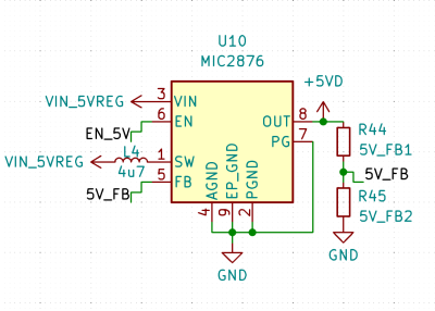
Some time ago, whiledesigning the PCBfor theSony Vaio replacement motherboard,I went on a quest to find a perfect 5 V boost regulator. Requirements are simple – output 5 V at about 2A, with input ranging from 3 V to 5 V, and when the input is 5 V, go into “100% duty” ( “pass-through” /” bypass” ) mode where the output is directly powered from the input, saving me from any conversion inefficiencies for USB port power when a charger is connected. Plus, a single EN pin, no digital configuration, small footprint, no BGA, no unsolicited services or offers – what more could one ask for.

As usual, I go to an online shop, set the parameters: single channel, all topologies that say “boost” in the name, output range, sort by price, download datasheets one by one and see what kind of nice chips I can find. Eventually, I found the holy grail chip for me,the MIC2876,originally from Micrel, now made by Microchip.

MIC2876 is a 5 V regulator with the exact features I describe above – to a T! It also comes with cool features, like a PG “Power good” output, bidirectional load disconnect (voltage applied to output won’t leak into input), EMI reduction and efficiency modes, and it’s decently cheap. I put it on the Sony Vaio board among five other regulators, ordered the board, assembled it, powered it up, and applied a positive logic level onto the regulator’s EN pin.

Immediately, I saw the regulator producing 3 V output accompanied by loud buzzing noise – as opposed to producing 5 V output without any audible noise. Here’s how the regulator ended up failing, how exactly I screwed up the design, and how I’m creating a mod board to fix it – so that the boards I meticulously assembled, don’t go to waste.

Some Background… Noise

Continue reading“Switching Regulators: Mistake Fi xing For Dummies”

I2C For Hackers: Digging Deeper

Last time, I gave youan overview of what you get from I2C,basics like addressing, interface speeds, and a breakdown of pullups. Today, let’s continue looking into I2C capabilities and requirements – level shifting, transfer types, and quirks like combined transfers or clock stretching.

Level Shifting

Continue reading“I2C For Hackers: Digging Deeper”

Switching Regulator Layout For Dummies

Last time, we went overswitching regulator basics– why they’re wonderful, how do you find a switching regulator chip for your purpose, and how to easily pick an inductor for one. Your datasheet should also tell you about layout requirements. However, it might not, or you might want to deviate from them – let’s go more in-depth on what those requirements are about.

Appreciate The Feedback

The two resistors on the right decide what your output voltage will be, and their output is noise-sensitive

There’s a few different switching regulator topologies. Depending on your regulator’s topology and how many components your chip contains, you might need some external components – maybe a Schottky diode, maybe a FET, or maybe even a FET pair. It’s often that the FET is built-in, and same goes for diodes, but with higher-current regulator (2 A to 3 A and above), it’s not uncommon to require an external one. For sizing up those, you’ll want to refer to the datasheet or existing boards.

Another thing is input and output capacitors – don’t skimp on those, because some regulators are seriously sensitive to the amount of capacitance they’re operating with. Furthermore, if you fail to consider things like capacitance dropping with voltage, you might make your regulator very unhappy – not that a linear regulator would be happy either, to be clear. We’ve covered an explainer on this recently –do check it out!

One thing you will likely need, is a feedback resistor divider – unless your switching regulator is pre-set for a certain voltage or is digitally controlled, you need to somehow point it to the right voltage, in an analog way. Quite a few switching regulators are set for a certain voltage output, but most of them aren’t, and they will want you to add a resistor divider to know what to output. There’s usually a formula for resistor divider calculation, so, pick a common resistor value, put it in as one of the resistors into the formula, get the other resistor value out of that formula, and see what’s the closest value you can actually buy. Don’t go below about 10 kΩ so that you don’t have unnecessary idle power consumption, but also don’t go too far above 100 kΩ to ensure good stability of the circuit.Continue reading“Switching Regulator Layout For Dummies”

All About USB-C: Connector Mechanics

There’s two cases when hackers have to think about USB-C connector mechanics. The first is when a USB-C connector physically breaks, and the second is when we need to put a connector on our own board. Let’s go through both of them.

Clean That Connector

What if a socket on your phone or laptop fails? First off, it could be due to dust or debris. There’s swabs you can buy to clean a USB-C connector; perhaps adding some isopropyl alcohol or other cleaning-suitable liquids, you can get to a “good enough” state. You can also reflow pins on your connector, equipped with hot air or a sharp soldering iron tip, as well as some flux – when it comes to mechanical failures, this tends to remedy them, even for a short period of time.
How could a connector fail, exactly? Well, one of the pins could break off inside the plastic, or just get too dirty to make contact. Consider a device with a USB-C charging and data socket, with USB 2.0 but without high-speed pairs – which is to say, sadly, the majority of the phones out there. Try plugging it into a USB-A charger using a USB-A to USB-C cable. Does it charge, even if slowly? Then, your VBUS pins are okay.

Plug it into a Type-C charger using a Type-C cable, and now the CC pins are involved. Does it charge in both orientations? Then both of your CC pins are okay. Does it charge in only one orientation? One of the CC pins has to be busted. Then, you can check USB 2.0 pins, used for data transfer and legacy charging. Plug the phone into a computer using a USB-A to USB-C cable. Does it enumerate as a device? Does it enumerate in both orientations? If not, you might want to clean D- and D+ pins specifically, maybe even both sets.Continue reading“All About USB-C: Connector Mechanics”

All You’ve Ever Wanted To Know About Compilers

They say that in order to understand recursion, you must first understand recursion. Once you master that concept, you might decide that it’s time to write your own compiler that can compile itself as a fun side project. According to [Warren] aka [DoctorWkt],who documented every step of writing this C compiler from scratch,a true compiler will be able to do that.

Some of the goals for the project included self-compiling, focusing on a real hardware platform, practicality, and simplicity. [Warren] outlines a lot of the theory of compilers as well, including all the lexical, grammar, and semantic analysis and then the final translation into assembly language, but really focuses on making this compiler one for practical use rather than just a theoretical implementation. He focuses on Intel x86-64 and 32-bit ARM platforms too, which are widely available.

This project is a long read and very thoroughly documented at around 100,000 words, so if you’ve ever been interested in compilers this is a great place to start. There are a lot of other great compiler tools floating around too,like the Compiler Explorerwhich shows you generated code as you write in a higher level language.

[viaHackaday.io]

Four Years Of Learning ESP8266 Development Went Into This Guide

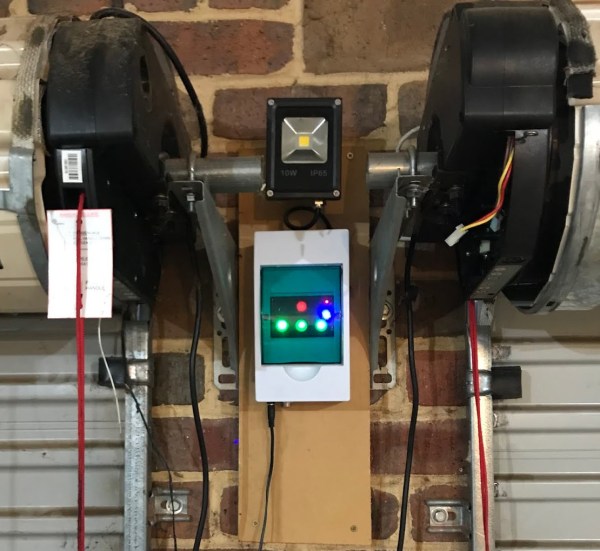
The ESP8266 is a great processor for a lot of projects needing a small microcontroller and Wi-Fi, all for a reasonable price and in some pretty small form factors. [Simon] used one to build a garage door opener. This project isn’t really about his garage door opener based on a cheap WiFi-enabled chip, though. It’s about the four year process he went through to learn how to develop on these chips, andluckily he wrote a guidethat anyone can use so that we don’t make the same mistakes he did.

The guide starts by suggesting which specific products are the easiest to use, and then moves on to some “best practices” for using these devices (with which we can’t argue much), before going through some example code. The most valuable parts of this guide especially for anyone starting out with these chips are the section which details how to get the web server up and running, and the best practices for developing HTML code for the tiny device (hint: develop somewhere else).

[Simon] also makes extensive use of the Chrome developers tools when building the HTML for the ESP. This is a handy trick even outside of ESP8266 development which might be useful for other tasks as well. Even though most of the guide won’t be new to anyone with experience with these boards, there are a few gems within it like this one that might help in other unrelated projects. It’s a good read and goes into a lot of detail about more than just the ESP chips. If you just want to open your garage door, though,you have lots of options.

Blacksmithing For The Uninitiated: Curves And Rings

You know the funny looking side of the anvil? That’s where the best curves come from. It’s called the anvil horn and is the blacksmith’s friend when bending steel and shaping it into curves.

The principle of bending a piece of steel stock is very easy to understand. Heat it up to temperature, and hammer it over a curved profile to the intended shape. A gentler touch is required than when you are shaping metal. That’s because the intent is to bend the metal rather than deform. Let’s take a look!

Continue reading“Blacksmithing For The Uninitiated: Curves And Rings”